Nissan Juke Service and Repair Manual : System
Body control system
BODY CONTROL SYSTEM : System Description
OUTLINE
• BCM (Body Control Module) controls the various electrical components. It inputs the information required to the control from CAN communication and the signal received from each switch and sensor.
• BCM has combination switch reading function for reading the operation status of combination switches (light, turn signal, wiper and washer) in addition to a function for controlling the operation of various electrical components.
It also has the signal transmission function as the passed point of signal and the power saving control function that reduces the power consumption with the ignition switch OFF.
• BCM is equipped with the diagnosis function that performs the diagnosis with CONSULT-III and various settings.
BCM CONTROL FUNCTION LIST
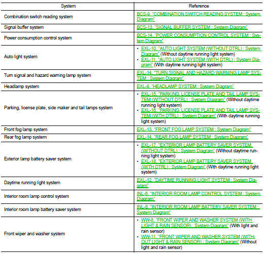
Combination switch reading system
COMBINATION SWITCH READING SYSTEM : System Diagram
NOTE
:
• *1: TAIL LAMP switch links lighting switch 1ST and 2ND positions.
• *2: “FR WIP INT/AT” is FR WIPER INT/AUTO.
COMBINATION SWITCH READING SYSTEM : System Description
OUTLINE
• BCM reads the status of the combination switch (light, turn signal, wiper and washer) and recognizes the status of each switch.
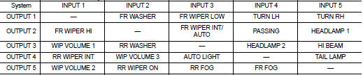
• BCM has a combination of 5 output terminals (OUTPUT 1 - 5) and 5 input terminals (INPUT 1 - 5). It reads a maximum of 20 switch status.
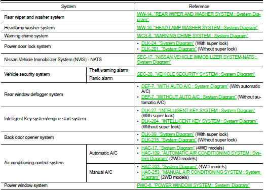
COMBINATION SWITCH MATRIX
Combination switch circuit
NOTE
:
• *1: TAIL LAMP switch links lighting switch 1ST and 2ND positions.
• *2: “FR WIP INT/AT” is FR WIPER INT/AUTO.
Combination switch INPUT-OUTPUT system list
NOTE
:
Headlamp has a dual system switch.
COMBINATION SWITCH READING FUNCTION
Description
• BCM reads the status of the combination switch at 10 ms interval normally.
NOTE
:
BCM reads the status of the combination switch at 60 ms interval when BCM is
controlled at low power consumption
control mode.
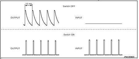
• BCM operates as follows and judges the status of the combination switch.
- It operates the transistor on OUTPUT side in the following order: OUTPUT 1 → 2 → 3 → 4 → 5, and outputs voltage waveform.
- The voltage waveform of OUTPUT corresponding to the formed circuit is input into the interface on INPUT side if any (1 or more) switches are ON.
- It reads this change of the voltage as the status signal of the combination switch.
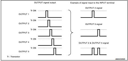
Operation Example
In the following operation example, the combination of the status signals of the
combination switch is replaced
as follows: INPUT 1 - 5 to “1 - 5” and OUTPUT 1 - 5 to “A - E”.
Example 1: When a switch (TAIL LAMP switch) is turned ON
• The circuit between OUTPUT 4 and INPUT 5 is formed when the TAIL LAMP switch is turned ON.
• BCM detects the combination switch status signal “5D” when the signal of OUTPUT 4 is input to INPUT 5.
• BCM judges that the TAIL LAMP switch is ON when the signal “5D” is detected.
Example 2: When some switches (TURN RH switch, TAIL LAMP switch) are turned ON • The circuits between OUTPUT 1 and INPUT 5 and between OUTPUT 4 and INPUT 5 are formed when the TURN RH switch and TAIL LAMP switch are turned ON.
• BCM detects the combination switch status signal “5AD” when the signals of OUTPUT 1 and OUTPUT 4 are input to INPUT 5.
• BCM judges that the TURN RH switch and TAIL LAMP switch are ON when the signal “5AD” is detected.
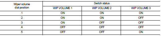
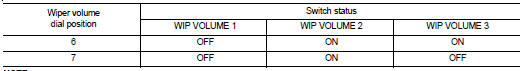
WIPER VOLUME DIAL POSITION
BCM judges the wiper volume dial 1 - 7 by the status of WIP VOLUME 1, 2 and 3 switches.
NOTE
:
For details of wiper volume dial position, refer to WW-8, "FRONT WIPER AND
WASHER SYSTEM (WITH LIGHT & RAIN SENSOR) :
System Description" (with light and rain sensor), WW-11, "FRONT WIPER AND WASHER
SYSTEM (WITHOUT LIGHT & RAIN SENSOR)
: System Description" (without light and rain sensor).
Signal buffer system
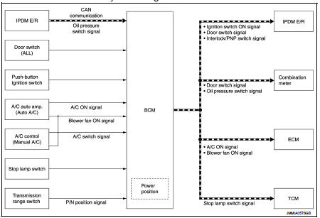
SIGNAL BUFFER SYSTEM : System Diagram
NOTE
:
Oil pressure switch is applied to diesel engine models.
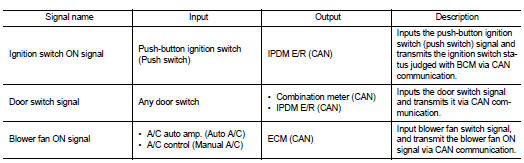
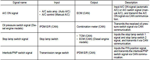
SIGNAL BUFFER SYSTEM : System Description
OUTLINE
BCM has the signal transmission function that outputs/transmits each input/received signal to each unit.
Signal transmission function list
Power consumption control system
POWER CONSUMPTION CONTROL SYSTEM : System Diagram
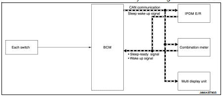
POWER CONSUMPTION CONTROL SYSTEM : System Description
OUTLINE
• BCM incorporates a power saving control function that reduces the power consumption according to the vehicle status.
• BCM switches the status (control mode) by itself with the power saving control function. It performs the sleep request to each unit (IPDM E/R, combination meter and multi display unit) that operates with the ignition switch OFF.
Normal mode (wake-up)
- CAN communication is normally performed with other units
- Each control with BCM is operating properly
CAN communication sleep mode (CAN sleep) - CAN transmission is stopped - Control with BCM only is operating
Low power consumption mode (BCM sleep) - Low power consumption control is active - CAN transmission is stopped
LOW POWER CONSUMPTION CONTROL WITH BCM
BCM reduces the power consumption with the following operation in the low power consumption mode.
• The reading interval of the each switches changes from 10 ms interval to 60 ms interval.
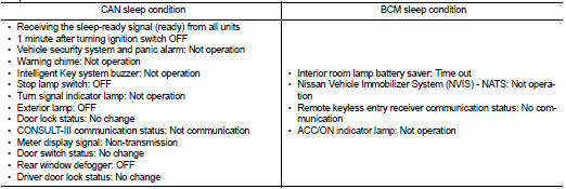
Sleep mode activation
• BCM receives the sleep-ready signal (ready) from IPDM E/R and combination
meter via CAN communication.
• BCM transmits the sleep wake up signal (sleep) to each unit when all of the CAN sleep conditions are fulfilled.
• Each unit stops the transmission of CAN communication with the sleep wake up signal. BCM is in CAN communication sleep mode.
• BCM is in the low power consumption mode and perform the low power consumption control when all of the BCM sleep conditions are fulfilled with CAN sleep condition.
Sleep condition
Wake-up operation
• BCM transmits sleep wake up signal (wake up) to each unit when any condition
listed below is established,
and then goes into normal mode from low power consumption mode.
• Each unit starts transmissions with CAN communication by receiving sleep wake up signals. Each unit transmit wake up signals to BCM with CAN communication to convey the start of CAN communication.
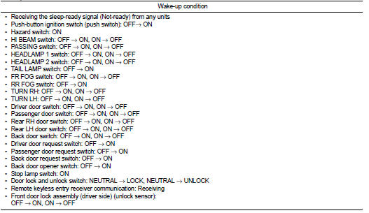
Wake-up condition
 Component parts
Body control system
BODY CONTROL SYSTEM : Component Parts Location
RHD MODELS
1. BCM
A. Behind of glove box (Left side)
LHD MODELS
1. BCM
A. Behind of instrument lower panel LH
(Left side) ...
 Diagnosis system (BCM)
Common item
COMMON ITEM : CONSULT-III Function (BCM - COMMON ITEM)
APPLICATION ITEM
CONSULT-III performs the following functions via CAN communication with BCM.
SYSTEM APPLICATION
BCM can perfo ...
Other materials:
Wiring diagram
CAN SYSTEM
Wiring Diagram
For connector terminal arrangements, harness layouts, and alphabets in a
(option abbreviation; if not
described in wiring diagram), refer to GI-12, "Connector Information/Explanation
of Option Abbreviation".
...
Front fender
Exploded View
1. Front fender assembly
2. Front fender stiffener
: Vehicle fr
Removal and Installation
REMOVAL
1. Remove front fillet molding. Refer to EXT-26, "FRONT FILLET MOLDING :
Removal and Installation".
2. Remove front bumper fascia assembly. Refer to EXT-13, "Remo ...
Rear-facing child restraint installation using the seat belts
WARNING
You must utilize the three-point seat belt equipped with an Automatic Locking Retractor (ALR) when securing a child restraint.
Failing to properly engage the ALR mode means the child restraint will not be secured effectively. This can allow the restraint to tip over or shift during ...
