Nissan Juke Service and Repair Manual : Component parts
Body control system
BODY CONTROL SYSTEM : Component Parts Location
RHD MODELS
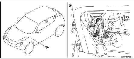
1. BCM
A. Behind of glove box (Left side)
LHD MODELS
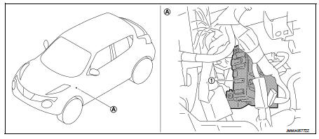
1. BCM
A. Behind of instrument lower panel LH (Left side)
Power consumption control system
POWER CONSUMPTION CONTROL SYSTEM : Component Parts Location
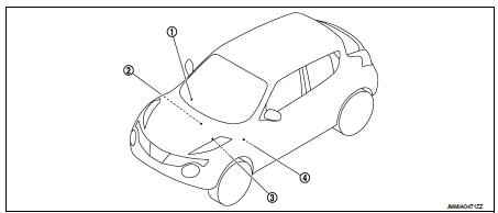
1. Combination meter 2. Multi display unit Refer to AV-96, "Component Parts Location".
3. IPDM E/R Refer to PCS-5, "Component Parts Location".
4. BCM Refer to BCS-6, "BODY CONTROL SYSTEM : Component Parts Location".

 System
Body control system
BODY CONTROL SYSTEM : System Description
OUTLINE
• BCM (Body Control Module) controls the various electrical components. It
inputs the information required to
the control f ...
Other materials:
RearView Monitor
CAMERA button (used to manually trigger the display views or adjust active screen brightness layouts)
MENU button (opens up global display preferences and system option configuration screens)
WARNING
Failure to follow all safety warnings and t ...
Parking brake switch
Component Function Check
1.CHECK PARKING BRAKE SWITCH OPERATION
Operate the parking brake lever. Then check that the brake warning lamp in
the combination meter turns ON/
OFF correctly.
Is the inspection result normal?
YES >> INSPECTION END
NO >> Proceed to BRC-208, "Diagn ...
Removal and installation
POWER WINDOW MAIN SWITCH
Removal and Installation
REMOVAL
1. Remove power window main switch finisher. Refer to INT-13, "Removal and
Installation".
2. Remove power window main switch (1) from power window
main switch finisher (2) using flat-head screw driver (A).
: Pawl
CAUTION:
...
