Nissan Juke Service and Repair Manual : Wiring diagram
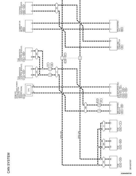
CAN SYSTEM
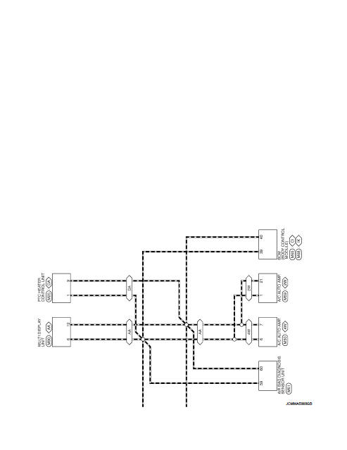
Wiring Diagram
For connector terminal arrangements, harness layouts, and alphabets in a
 (option abbreviation; if not
described in wiring diagram), refer to GI-12, "Connector Information/Explanation
of Option Abbreviation".
 System
Can communication system
CAN COMMUNICATION SYSTEM : System Diagram
CAN COMMUNICATION SYSTEM : System Description
Description
ÔÇó CAN (Controller Area Network) is a serial communication line for ...
 Basic inspection
DIAGNOSIS AND REPAIR WORKFLOW
Interview Sheet
NOTE:
Refer to LAN-17, "Trouble Diagnosis Procedure" for how to use interview sheet.
...
Other materials:
ASCD brake switch
Component Function Check
1.CHECK ASCD BRAKE SWITCH FUNCTION
With CONSULT-III
1. Turn ignition switch ON.
2. Select ÔÇťENGINEÔÇŁ using CONSULT-III.
3. Select ÔÇťBRAKE SW1ÔÇŁ in ÔÇťDATA MONITORÔÇŁ mode.
4. Check ÔÇťBRAKE SW1ÔÇŁ indication under the following conditions.
Without CONSULT-III
1 ...
Precaution
Precaution for Supplemental Restraint System (SRS) "AIR BAG" and "SEAT
BELT
PRE-TENSIONER"
The Supplemental Restraint System such as ÔÇťAIR BAGÔÇŁ and ÔÇťSEAT BELT PRE-TENSIONERÔÇŁ,
used along
with a front seat belt, helps to reduce the risk or severity of injury to the
...
P0715 input speed sensor A
DTC Logic
DTC DETECTION LOGIC
DTC CONFIRMATION PROCEDURE
CAUTION:
Always drive vehicle at a safe speed.
NOTE:
If ÔÇťDTC CONFIRMATION PROCEDUREÔÇŁ has been previously performed, always turn
ignition switch
OFF and wait at least 10 seconds before performing the next test.
After the repai ...
