Nissan Juke Service and Repair Manual : Removal and Installation Procedure for CVT Unit Connector
REMOVAL
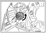
Rotate bayonet ring (1) counterclockwise, pull out CVT unit harness connector (2) upward and remove it.
INSTALLATION
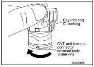
1. Align Δ marking on CVT unit harness connector terminal body with marking on bayonet ring, insert CVT unit harness connector, and then rotate bayonet ring clockwise.
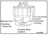
2. Rotate bayonet ring clockwise until Δ marking on CVT unit harness connector terminal body is aligned with the slit on bayonet ring as shown in the figure (correctly fitting condition), install CVT unit harness connector to CVT unit harness connector terminal body.
CAUTION:
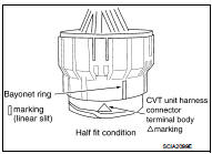
• Securely align Δ marking on CVT unit harness connector
terminal body with bayonet ring slit. Then, be careful not
to make a half fit condition as shown in the figure.
• Never mistake the slit of bayonet ring for other dent portion.
 Precaution for G Sensor Removal/Installation or Replacement
CAUTION:
To remove/install or replace G sensor, refer to TM-182, "Description". ...
 Precaution
NOTE:
If any malfunction occurs in the RE0F10A model transaxle, replace the entire
transaxle assembly.
• Before connecting or disconnecting the TCM harness connector,
turn ignition switch OFF a ...
Other materials:
P0340 CMP sensor (PHASE)
DTC Logic
DTC DETECTION LOGIC
DTC CONFIRMATION PROCEDURE
1.PRECONDITIONING
If DTC Confirmation Procedure has been previously conducted, always perform
the following procedure
before conducting the next test.
1. Turn ignition switch OFF and wait at least 10 seconds.
2. Turn ignition swit ...
Precautions on charging
WARNING
If you utilize medical electronic devices, such as an implantable cardiac pacemaker or an implantable cardiovascular defibrillator, please consult with the device manufacturer regarding potential electromagnetic interference. Charging your Nissan Leaf may impact the operation ...
Component parts
Component Parts Location
1. Push-button ignition switch
2. Stop lamp switch
Refer to BRC-9, "Component Parts
Location" (without EPS), BRC-97,
"Component Parts Location" (with
EPS)
3. IPDM E/R
Refer to PCS-5, "Component Parts
Location"
4. Transmission range ...
