Nissan Juke Service and Repair Manual : Unit disassembly and assembly
Torque converter and converter housing oil seal
Exploded View
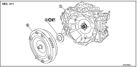
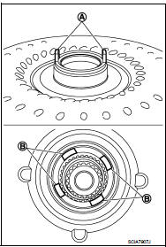
1. Transaxle assembly 2. Converter housing oil seal 3. Torque converter
 : Always replace after every
disassembly.
 : Apply CVT Fluid NS-2.
Disassembly
1. Remove transaxle assembly. Refer to TM-301, "Removal and Installation".
2. Remove torque converter from transaxle assembly.
CAUTION:
Never damage bush on the inside of torque converter sleeve when removing torque
converter.
3. Remove converter housing oil seal using a flat-bladed screwdriver.
CAUTION:
Be careful not to scratch converter housing.
Assembly
Note the following, and install in the reverse order of removal.
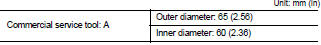
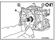
ÔÇó Drive converter housing oil seal (1) evenly using a drift (A) (commercial service tool) so that converter housing oil seal protrudes by the dimension (B) respectively.
2 : Transaxle assembly

NOTE
:
Converter housing oil seal pulling direction is used as the reference.
ÔÇó After completing installation, check for CVT fluid leakage and CVT fluid level. Refer to TM-184, "Inspection".
ÔÇó Attach the pawl (A) of the torque converter to the drive sprocket hole (B) on the transaxle assembly side.
CAUTION:
ÔÇó Rotate the torque converter for installing torque converter.
ÔÇó Never damage the bushing inside the torque converter sleeve when installing the converter housing oil seal.
Inspection
INSPECTION AFTER INSTALLATION
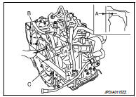
ÔÇó After inserting a torque converter to the CVT, check dimension (A) with in the reference value limit.
B : Scale
C : Straightedge
Dimension (A) : Refer to TM-308, "Torque Converter".
 Unit removal and installation
Transaxle assembly
Exploded View
1. CVT fluid level gauge
2. CVT fluid charging pipe
3. O-ring
4. Transaxle assembly
5. Air breather hose
A. For tightening torque, refer to TM-301, "R ...

Other materials:
System
Body control system
BODY CONTROL SYSTEM : System Description
OUTLINE
ÔÇó BCM (Body Control Module) controls various electrical components.It
receives the information required from
CAN communication and the signals received from each switch and sensor.
ÔÇó BCM has a combination switch reading ...
Precaution
Precaution for Supplemental Restraint System (SRS) "AIR BAG" and "SEAT
BELT
PRE-TENSIONER"
The Supplemental Restraint System such as ÔÇťAIR BAGÔÇŁ and ÔÇťSEAT BELT PRE-TENSIONERÔÇŁ,
used along
with a front seat belt, helps to reduce the risk or severity of injury to the
...
Multiport Fuel Injection System or Engine Control System
ÔÇó Before connecting or disconnecting any harness connector for the
multiport fuel injection system or ECM:
Turn ignition switch to ÔÇťOFFÔÇŁ position.
Disconnect negative battery terminal. Otherwise, there may be damage to ECM.
ÔÇó Before disconnecting pressurized fuel line from fuel pump to ...
