Nissan Juke Service and Repair Manual : Structure and operation
Transaxle : Cross-Sectional View
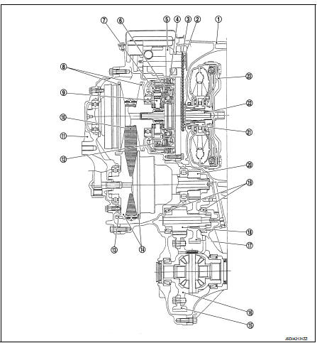
1. Converter housing
2. Driven sprocket
3. Chain
4. Reverse brake
5. Oil pump
6. Forward clutch
7. Planetary carrier
8. Primary pulley
9. Sun gear
10. Steel belt
11. Side cover
12. Internal gear
13. Parking gear
14. Secondary pulley
15. Final gear
16. Differential case
17. Idler gear
18. Reduction gear
19. Taper roller bearing
20. Output gear
21. Drive sprocket
22. Input shaft
23. Torque converter
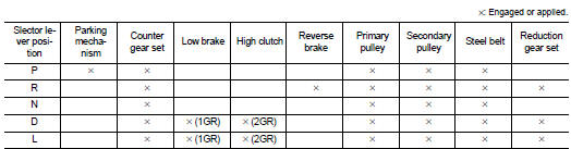
Transaxle : Operation Status
Transaxle : Transaxle Mechanism
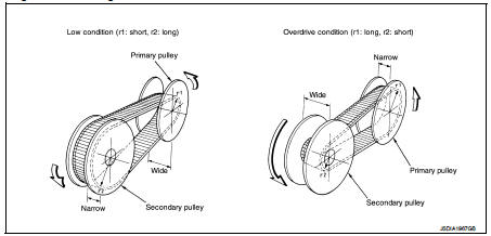
BELT & PULLEY
Mechanism
It is composed of a pair of pulleys (the groove width is changed freely in the
axial direction) and the steel belt
(the steel plates are placed continuously and the belt is guided with the
multilayer steel rings on both sides).
The groove width changes according to wrapping radius of steel belt and pulley from low status to overdrive status continuously with non-step. It is controlled with the oil pressures of primary pulley and secondary pulley.
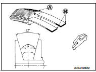
Steel belt
It is composed of multiple steel plates (A) and two steel rings (B)
stacked to a several number. The feature of this steel belt transmits
power with compression of the steel plate in contrast with transmission
of power in pulling with a rubber belt. Friction force is required
with the pulley slope to transmit power from the steel plate. The force
is generated with the following mechanism:
Oil pressure applies to the secondary pulley to nip the plate. ⇒The
plate is pushed and extended outward. ⇒The steel ring shows withstands.
⇒Pulling force is generated on the steel ring. ⇒The plate of the primary pulley is nipped between the pulley. ⇒Friction force is generated between the steel belt and the pulley.
Therefore, responsibilities are divided by the steel plate that transmits the power with compression and the steel ring that maintains necessary friction force. In this way, the tension of the steel ring is distributed on the entire surface and stress variation is limited, resulting in good durability.
Pulley
The primary pulley (input shaft side) and the secondary pulley (output shaft
side) have the shaft with slope
(fixed cone surface), movable sheave (movable cone surface that can move in the
axial direction) and oil pressure
chamber at the back of the movable sheave.
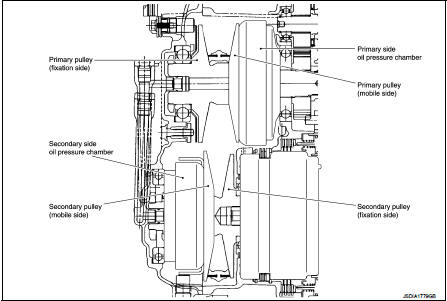
Pulley gear shifting operation • Pulley gear shifting operation The movable sheave slides on the shaft to change the groove width of the pulley. Input signals of engine load (accelerator pedal opening), engine revolution and gear ratio (vehicle speed) change the operation pressures of the primary pulley and the secondary pulley, and controls the pulley groove width. Along with change of the pulley groove width, the belt contact radius is changed. This allows continuous and stepless gear shifting from low to overdrive. “The contact radius ratio of each pulley in contact with the belt x auxiliary gearbox gear ratio” is the gear ratio.
AUXILIARY GEARBOX MECHANISM
1st, 2nd and reverse gears are changed with the planetary gear mechanism.
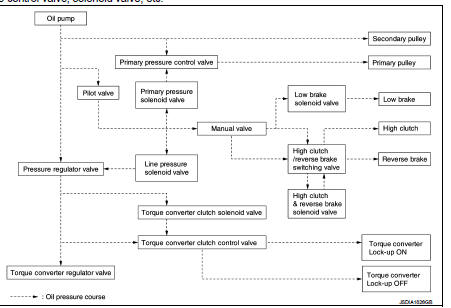
Transaxle : Oil Pressure System
Oil pressure required for operation of the transaxle transmission mechanism is generated by oil pump, oil pressure control valve, solenoid valve, etc.
Transaxle : Component Description
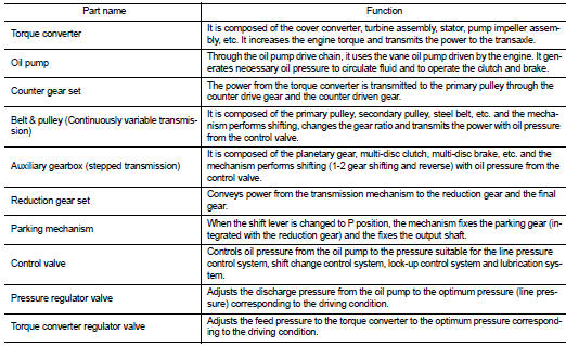
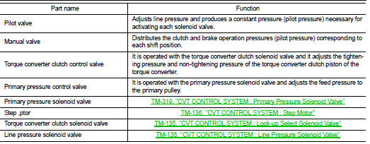
 Component parts
CVT control system : Component Parts Location
1. Multi display unit (MDU)*
Refer to DMS-3, "Component Parts
Location".
2. Combination meter 3. Manual mode indicator
(On the combinatio ...
 System
CVT control system : System Diagram
CVT control system : System Description
The CVT senses vehicle operating conditions through various sensors. It
always controls the optimum shift
position an ...
Other materials:
System
System Diagram
MODELS WITH USB CONNECTION FUNCTION
NOTE:
An antenna base integrated with radio antenna amp. is adopted.
MODELS WITHOUT USB CONNECTION FUNCTION
NOTE:
An antenna base integrated with radio antenna amp. is adopted.
System Description
AUDIO SYSTEM
Audio functions
AUDIO ...
Intelligent Cruise Control (ICC) (for vehicles with ProPILOT Assist)
WARNING
Failure to strictly adhere to these warnings and operational instructions regarding the Intelligent Cruise Control (ICC) system in your Nissan Leaf could result in a serious accident, personal injury, or death.
The ICC system is strictly a driver-assistance aid; it is not ...
Front door
Exploded View
1. Front door panel
2. Grommet
3. Door hinge (upper)
4. Door hinge (lower)
5. Door check link
6. Bumper rubber
7. Door pad
8. Door striker
9. TORX bolt
10. Grommet
: Do not reuse
: N·m (kg-m, in-lb)
: N·m (kg-m, ft-lb)
: Body grease
Door assembly
DOOR ASSEMBLY ...
