Nissan Juke Service and Repair Manual : Structure and operation
Sectional View
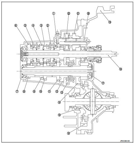
1. 3rd input gear
2. 3rd-4th synchronizer hub assembly
3. 4th input gear
4. 5th input gear
5. 5th-6th synchronizer hub assembly
6. 6th input gear
7. Transaxle case
8. 6th main gear
9. 5th main gear
10. 4th main gear
11. 3rd main gear
12. 2nd main gear
13. 1st-2nd synchronizer hub assembly
14. 1st main gear
15. Differential
16. Final gear
17. Mainshaft
18. Input shaft
19. Clutch housing
20. Reverse idler shaft
21. Reverse input gear
22. Reverse output gear
System Description
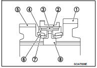
TRIPLE-CONE SYNCHRONIZER
Triple-cone synchronizers are adopted for the 1st and the 2nd gears to reduce operating force of the shifter lever.
1 : 1st main gear
2 : 1st-2nd coupling sleeve
3 : Insert key
4 : Outer baulk ring
5 : 2nd main gear
6 : Synchronizer cone
7 : Inner baulk ring
8 : 1st-2nd synchronizer hub
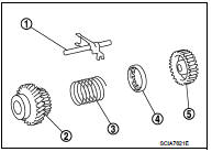
REVERSE GEAR NOISE PREVENTION FUNCTION (SYNCHRONIZING METHOD)
Reverse gear assembly consists of reverse input gear, return spring, reverse baulk ring, and reverse output gear. When the shifter lever is shifted to the reverse position, the construction allows smooth shift operation by stopping the reverse idler shaft rotation by frictional force of synchronizer.
1 : Reverse fork rod
2 : Reverse output gear
3 : Return spring
4 : Reverse baulk ring
5 : Reverse input gear
 Component parts
Component Parts Location
POSITION SWITCH
1 : Position switch
...
 DTC/Circuit diagnosis
POSITION SWITCH ...
Other materials:
Back door trim
Exploded View
1. Back door side finisher RH
2. Rear parcel shelf finisher
3. Back door side finisher LH
4. Back door lower finisher
5. Emergency lid
6. Back door pull handle
: Clip
: Pawl
Back door pull handle : Removal and Installation
REMOVAL
CAUTION:
• When removing, always us ...
Power door lock system
System Diagram
System Description
DOOR LOCK FUNCTION
• The door lock and unlock switch (driver side) is build into power window
main switch.
• Interlocked with the locking operation of door lock and unlock switch, door
lock actuators of all doors are
locked.
• Interlocked with the ...
Loss of power
Description
CHART 12: LOSS OF POWER
Diagnosis Procedure
1.CHECK FUEL
Check that the fuel reservoir is correctly filled and with the right fuel.
>> GO TO 2.
2.CHECK FUEL FILTER
Check the correctness of the fuel filter.
Is the fuel filter correct?
Yes >> GO TO 3.
No >& ...
