Nissan Juke Service and Repair Manual : Wiring diagram
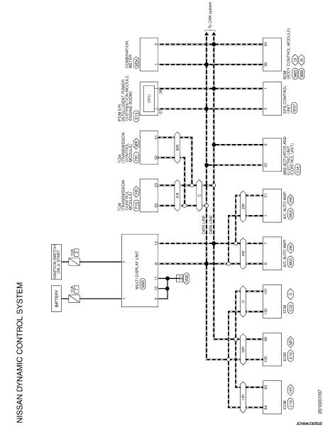
NISSAN DYNAMIC CONTROL SYSTEM
Wiring Diagram
For connector terminal arrangements, harness layouts, and alphabets in a
 (option abbreviation; if not
described in wiring diagram), refer to GI-12, "Connector Information/Explanation
of Option Abbreviation".
 Multi display unit
Reference Value
VALUES ON THE DIAGNOSIS TOOL
• *1:MR16DDT
• *2: This is not used to determine ON/OFF of the indicator lamp.
TERMINAL LAYOUT
PHYSICAL VALUES
DTC Inspection Priority Ch ...
 Basic inspection
DIAGNOSIS AND REPAIR WORK FLOW
Work Flow
DESCRIPTION OF TROUBLE DIAGNOSIS FLOWCHART
DETAILS OF TROUBLE DIAGNOSIS FLOWCHART
1.OBTAIN INFORMATION ABOUT SYMPTOM
Interview the customer to obtain as ...
Other materials:
Front door lock
Exploded View
1. Door key cylinder assembly (driver
side)
Outside handle escutcheon (passenger
side)
2. Outside handle
3. Front gasket
4. Inside handle
5. TORX bolt
6. Door lock assembly
7. Key rod (driver side)
8. Outside handle bracket
9. Rear gasket
10. Key rod protector (driv ...
System setting
Temperature Setting Trimmer
DESCRIPTION
If the temperature felt by the customer is different from the air flow
temperature controlled by the temperature
setting, the A/C auto amp. control temperature can be adjusted to compensate for
the temperature setting.
HOW TO SET
With CONSULT-III
P ...
Cleaning exterior
In order to maintain the appearance of your vehicle, it is important to take
proper care of it.
To protect the paint surfaces, wash your vehicle as soon as you can:
• after a rainfall to prevent possible damage from acid rain
• after driving on coastal roads
• when contaminan ...
