Nissan Juke Service and Repair Manual : Multi display unit
Reference Value
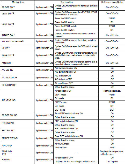
VALUES ON THE DIAGNOSIS TOOL
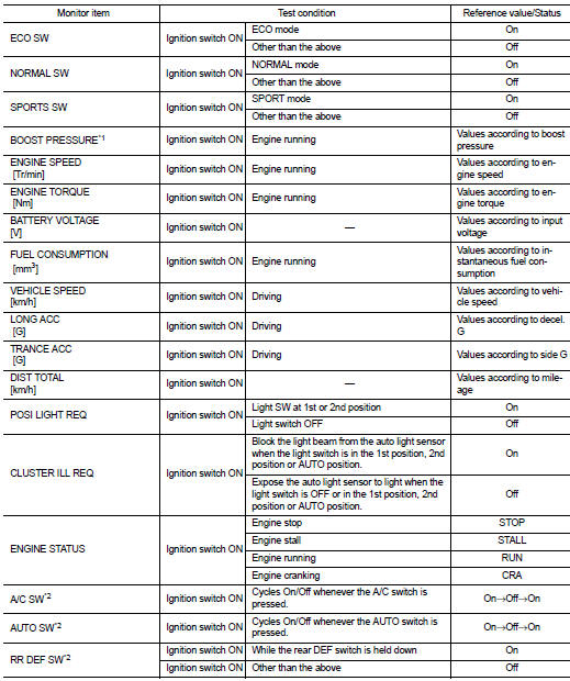
• *1:MR16DDT
• *2: This is not used to determine ON/OFF of the indicator lamp.
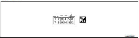
TERMINAL LAYOUT
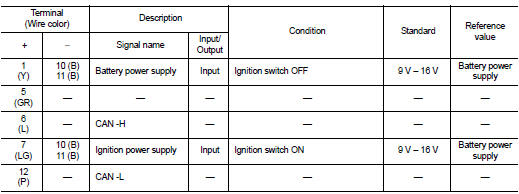
PHYSICAL VALUES
DTC Inspection Priority Chart
When multiple DTCs are displayed simultaneously, check one by one according to the following priority list.
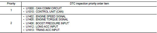
*: MR16DDT
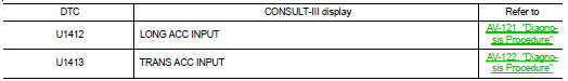
DTC Index
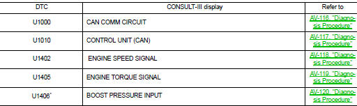
*: MR16DDT

 Wiring diagram
NISSAN DYNAMIC CONTROL SYSTEM
Wiring Diagram
For connector terminal arrangements, harness layouts, and alphabets in a
(option abbreviation; if not
described in wiring diagram), refer to GI-12, &q ...
Other materials:
Exploded View
M/T models
1. Clamp
2. Water hose
3. Oil cooler
4. Water hose
N·m (kg-m, in-lb)
CVT models
1. Clamp
2. Water hose
3. Oil cooler
4. Water hose
5. Water hose
6. Heater thermostat
7. Water hose
A. To CVT oil warmer
: N·m (kg-m, in-lb)
...
Power window main switch
Reference Value
TERMINAL LAYOUT
PHYSICAL VALUES
POWER WINDOW MAIN SWITCH
Fail Safe
FAIL-SAFE CONTROL
Switches to fail-safe control when malfunction is detected in encoder signal
that detects up/down speed and
direction of door glass. Switches to fail-safe control when error beyond
r ...
Parking brake
WARNING
• Be sure the parking brake is fully released before driving. Failure to do
so can cause brake failure and lead to an accident.
• Do not release the parking brake from outside the vehicle.
• Do not use the shift lever in place of the parking brake. When parking, be sure
th ...
