Nissan Juke Service and Repair Manual : Exhaust manifold
Exploded View
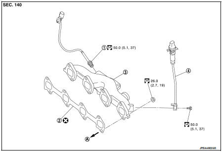
1. Exhaust gas temperature sensor 1
2. Gasket
3. Exhaust manifold
4. Exhaust gas pressure sensor 1
A. To cylinder head
 : N┬Ěm (kg-m, ft-lb)
 : Always replace after every
disassembly.
Removal and Installation
REMOVAL
1. Remove turbocharger assembly. Refer to EM-284, "Exploded View".
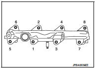
2. Loosen exhaust manifold mounting nuts in the reverse order as shown.
3. Remove exhaust manifold.
INSTALLATION
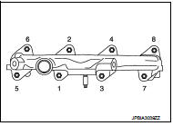
1. Tighten the mounting nuts in numerical order as shown.
2. Install in reverse order of removal after this step.
Inspection
Start engine and raise engine speed to check no exhaust emission leaks.
 Turbocharger
Exploded View
1. Exhaust manifold
2. Turbocharger
3. Gasket
4. Turbocharger outlet duct
5. Oil outlet hose
6. Clamp
7. Oil return pipe
8. Gasket
9. Washer
10. Oil supply tube
11. O ...
 Oil pan
Exploded View
1. Baffle plate
2. Gasket
3. Oil pan
4. O-ring
5. Drain plug
6. Oil level gauge guide
7. Transaxle
8. Crankshaft position sensor (POS)
: N┬Ěm (kg-m, ft-lb)
: N┬Ěm (kg-m, ...
Other materials:
Remote keyless entry receiver
Component Function Check
1.CHECK FUNCTION
1. Select ÔÇťINTELLIGENT KEYÔÇŁ of ÔÇťBCMÔÇŁ using CONSULT-III.
2. Select ÔÇťRKE OPE COUN1ÔÇŁ in ÔÇťDATA MONITORÔÇŁ mode.
3. Check that the function operates normally according to the following
conditions.
Is the inspection result normal?
YES >& ...
B1170, B1171, B1172, B1173, B1174, B1175 diagnosis sensor uniT
DTC Logic
DTC DETECTION LOGIC
DTC CONFIRMATION PROCEDURE
1.CHECK SELF-DIAG RESULT
With CONSULT-III
1. Turn ignition switch ON.
2. Perform ÔÇťSelf Diagnostic ResultÔÇŁ mode of ÔÇťAIR BAGÔÇŁ using CONSULT-III.
Without CONSULT-III
1. Turn ignition switch ON.
2. Check the air bag warning la ...
B1184 lap Pre-tensioner LH
DTC Logic
DTC CONFIRMATION PROCEDURE
1.CHECK SELF-DIAGNOSTIC RESULT
With CONSULT-III
1. Turn ignition switch ON.
2. Perform ÔÇťSelf Diagnostic ResultÔÇŁ mode of ÔÇťAIR BAGÔÇŁ using CONSULT-III.
Without CONSULT-III
1. Turn ignition switch ON.
2. Check the air bag warning lamp status. Refe ...
