Nissan Juke Service and Repair Manual : Oil pan
Exploded View
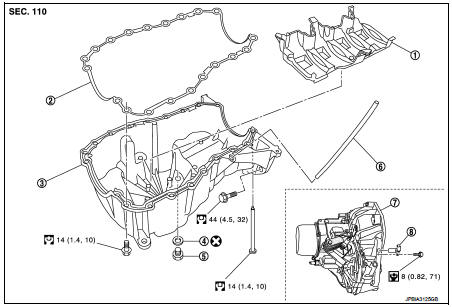
1. Baffle plate
2. Gasket
3. Oil pan
4. O-ring
5. Drain plug
6. Oil level gauge guide
7. Transaxle
8. Crankshaft position sensor (POS)
 : N┬Ęm (kg-m, ft-lb)
 : N┬Ęm (kg-m, in-lb)
 : Always replace after every
disassembly.
Removal and Installation
REMOVAL
CAUTION:
Never drain engine oil when the engine is hot to avoid the danger of being
scalded.
1. Remove engine under cover.
2. Remove RH front wheel. Refer to WT-7, "Exploded View".
3. Remove fender protector RH. Refer to EXT-22, "Exploded View".
4. Remove engine mounting bracket. Refer to EM-326, "Exploded View".
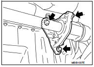
5. Remove center bearing bracket as shown.
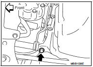
6. Remove A/C compressor bracket mounting bolt as shown.
7. Remove oil level gauge guide.
8. Drain engine oil. Refer to LU-34, "Draining".
CAUTION:
Perform when engine is cold.
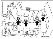
9. Remove oil pan and transaxle joint bolts.
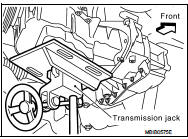
10. Support the engine bottom of the oil pan with a transmission jack etc.
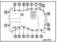
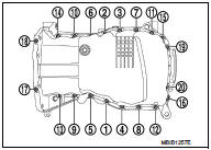
11. Remove oil pan bolt reverse order as shown.
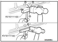
ŌĆó Insert seal cutter (special service tool) between upper oil pan and cylinder block. Slide tool by tapping on the side of the tool with a hammer.
CAUTION:
Exercise care not to damage mating surface.
12. Remove oil pan and baffle plate.
INSTALLATION
ŌĆó Install in the reverse order of removal paying attention to the following.
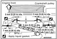
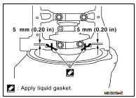
1. Apply liquid gasket as shown.
ŌĆó Use Genuine Liquid Gasket or equivalent.
2. Install baffle plate.
3. Install oil pan.
ŌĆó Tighten the mounting bolts of oil pan on the clutch housing without locking.
ŌĆó Tighten the bolts in the numerical order shown in the figure.
 : 14 N┬Ęm (1.4 kg-m, 10 ft-lb)
ŌĆó Tighten the mounting bolts of oil pan on the clutch housing.
 : 44 N┬Ęm (4.5 kg-m, 10 ft-lb)
4. At least 30 minutes after oil pan is installed, pour engine oil.
Inspection
INSPECTION AFTER REMOVAL
Clean oil pump assembly if any object attached.
INSPECTION AFTER INSTALLATION
ŌĆó Inspection the engine oil level. Refer to LU-33, "Inspection".
ŌĆó Start the engine, and make sure there is no leak of engine oil. Refer to LU-33, "Inspection".
 Exhaust manifold
Exploded View
1. Exhaust gas temperature sensor 1
2. Gasket
3. Exhaust manifold
4. Exhaust gas pressure sensor 1
A. To cylinder head
: N┬Ęm (kg-m, ft-lb)
: Always replace after every
disa ...
 Glow plug
Exploded View
1. Glow plug
Engine front
: N┬Ęm (kg-m, ft-lb)
Removal and Installation
REMOVAL
CAUTION:
Remove glow plug only if necessary. If carbon adheres, it may be stuck and
broken.
1 ...
Other materials:
Rear wiper auto stop signal circuit
Component Function Check
1.CHECK REAR WIPER (AUTO STOP) OPERATION
CONSULT-III DATA MONITOR
1. Select ŌĆ£WIPERŌĆØ of BCM data monitor item.
2. Operate the rear wiper.
3. Check that ŌĆ£RR WIPER STOPŌĆØ changes to ŌĆ£OnŌĆØ and ŌĆ£OffŌĆØ linked with the wiper
operation.
Is the status of item n ...
Precaution
Precautions for Drive Shaft
ŌĆó Observe the following precautions when disassembling and assembling drive
shaft.
- Never disassemble joint sub-assembly because it is non-overhaul parts.
- Perform work in a location which is as dust-free as possible.
- Clean the parts, before disassembling an ...
System
AUTO RETRACTABLE DOOR MIRORR FUNCTION
AUTO RETRACTABLE DOOR MIRORR FUNCTION : System Diagram
AUTO RETRACTABLE DOOR MIRORR FUNCTION : System Description
BCM retracts door mirror when door lock signal is received from Intelligent
Key or door request switch.
OPERATION CONDITION
The system oper ...
