Nissan Juke Service and Repair Manual : Basic inspection
DIAGNOSIS AND REPAIR WORK FLOW
Work Flow
DESCRIPTION OF TROUBLE DIAGNOSIS FLOWCHART
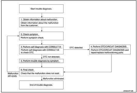
DETAILS OF TROUBLE DIAGNOSIS FLOWCHART
1.OBTAIN INFORMATION ABOUT SYMPTOM
Interview the customer to obtain as much information as possible about the conditions and environment under which the malfunction occurs.
>> GO TO 2.
2.CHECK SYMPTOM
• Check the symptom based on the information obtained from the customer.
• Check if any other malfunctions are present.
>> GO TO 3.
3.CONSULT-III SELF-DIAGNOSIS
Perform “MULTI DISPLAY” “self diagnosis” by connecting CONSULT-III.
NOTE: If “CAN COM CIRC [U1000]” is displayed, start the diagnosis from the CAN communication system. AV-116, "Diagnosis Procedure".
Is any DTC No. displayed? YES >> GO TO 4.
NO >> GO TO 5.
4.DTC/SYSTEM DIAGNOSIS
Perform a DTC/system diagnosis and repair or replace any malfunctioning part.
>> GO TO 6.
5.PERFORM DIAGNOSIS BY SYMPTOM
Perform a diagnosis by symptom and repair or replace any malfunctioning part.
>> GO TO 6.
6.FINAL CHECK
Check that the multi display unit functions normally.
Does it operate normally? YES >> End of trouble diagnosis NO >> GO TO 2.
 Wiring diagram
NISSAN DYNAMIC CONTROL SYSTEM
Wiring Diagram
For connector terminal arrangements, harness layouts, and alphabets in a
(option abbreviation; if not
described in wiring diagram), refer to GI-12, &q ...

Other materials:
Door does not lock/unlock with door key cylinder operation
Diagnosis Procedure
1.CHECK POWER DOOR LOCK OPERATION
Check power door lock operation.
Does door lock/unlock with door lock and unlock switch?
YES >> GO TO 2.
NO >> Go to DLK-110, "ALL DOOR : Diagnosis Procedure".
2.CHECK UNLOCK SENSOR
Check unlock sensor.
Refer ...
Front suspension member
Exploded View
2WD
1. Front suspension member
2. Damper assembly*
3. Rebound stopper rubber
4. Washer
5. Member stay
6. Rebound stopper
: N·m (kg-m, ft-lb)
*: For K9K models
4WD
1. Front suspension member
2. Rebound stopper rubber
3. Washer
4. Member stay
5. Rebound stopper ...
Magnet clutch
Component Function Check
1.CHECK MAGNET CLUTCH OPERATION
Perform auto active test of IPDM E/R. Refer to PCS-12, "Diagnosis
Description" (with Intelligent Key) or PCS-
43, "Diagnosis Description" (without Intelligent Key).
Does it operate normally?
YES >> INSPECTION ...
