Nissan Juke Service and Repair Manual : Component parts
Component Parts Location
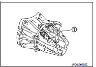
POSITION SWITCH
1 : Position switch

 Structure and operation
Sectional View
1. 3rd input gear
2. 3rd-4th synchronizer hub assembly
3. 4th input gear
4. 5th input gear
5. 5th-6th synchronizer hub assembly
6. 6th input gear
7. Transaxle case
8. 6th ...
Other materials:
Parking brake switch
Component Function Check
1.CHECK PARKING BRAKE SWITCH OPERATION
Operate the parking brake lever. Then check that the brake warning lamp in
the combination meter turns ON/
OFF correctly.
Is the inspection result normal?
YES >> INSPECTION END
NO >> Proceed to BRC-70, "Diagno ...
Li-ion battery available charge gauge
This gauge provides an accurate real-time indication of the available energy stored in the Li-ion battery, which is necessary to power your Nissan Leaf.
This figure represents the current state of charge (SOC) of the battery expressed as a percentage.
...
Cleaning interior
Maintaining the cabin of your Nissan Leaf requires periodic attention to preserve the comfort and aesthetic quality of the materials. To begin, remove loose dust and debris from the interior trim, dashboard, plastic panels, and seat surfaces using a high-quality vacuum cleaner with a soft-brush atta ...
