Nissan Juke Service and Repair Manual : Door cable
Exploded View
LEFT SIDE
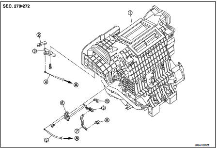
1. A/C unit assembly
2. Intake door lever
3. Intake door link
4. Intake door cable
5. Air mix door cable
6. Air mix door link
7. Air mix door rod
8. Lower air mix door lever
9. Upper air mix door lever
10. Max. cool door
A. To A/C control
RIGHT SIDE
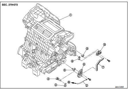
1. A/C unit assembly
2. Mode door cable
3. Foot door lever
4. Foot door link
5. Side ventilator door lever
6. Mode door main link
7. Mode door main link adapter rod
8. Center ventilator door lever
9. Defroster door lever
10. Mode door main link adapter
A. To A/C control
Intake door cable : Removal and Installation
REMOVAL
1. Disconnect intake door cable from A/C control. Refer to HAC-308, "Exploded View".
2. Remove instrument lower panel LH. Refer to IP-13, "Removal and Installation".
(LHD models)
3. Remove glove box assembly. Refer to IP-13, "Removal and Installation". (RHD
models)
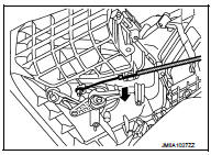
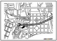
4. Disconnect intake door cable from A/C unit assembly as shown
by the arrow in the figure, and then remove intake door cable.
INSTALLATION
Install in the reverse order of removal.
Mode door cable : Removal and Installation
REMOVAL
1. Disconnect mode door cable from A/C control. Refer to HAC-308, "Exploded View".
2. Remove glove box assembly. Refer to IP-13, "Removal and Installation". (LHD
models)
3. Remove instrument panel RH. Refer to IP-13, "Removal and Installation". (RHD
models)
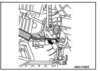
4. Disconnect mode door cable from A/C unit assembly as shown
by the arrow in the figure, and then remove mode door cable.
INSTALLATION
Install in the reverse order of removal.
Air mix door cable : Removal and Installation
REMOVAL
1. Disconnect air mix door cable from A/C control. Refer to HAC-308, "Exploded View".
2. Remove instrument panel LH. Refer to IP-13, "Removal and Installation". (LHD
models)
3. Remove glove box assembly. Refer to IP-13, "Removal and Installation". (RHD
models)
4. Disconnect air mix door cable from A/C unit assembly as shown
by the arrow in the figure, and then remove air mix door cable.
INSTALLATION
Install in the reverse order of removal.
 Blower fan resistor
Exploded View
1. A/C unit assembly
2. Fan control amp.*1
3. Blower fan resistor*2
4. Blower motor
5. Blower motor cover
• *1: Automatic air conditioner
• *2: Manual air conditioner
R ...

Other materials:
P0102, P0103 MAF sensor
DTC Logic
DTC DETECTION LOGIC
DTC CONFIRMATION PROCEDURE
1.PRECONDITIONING
If DTC Confirmation Procedure has been previously conducted, always perform
the following procedure
before conducting the next test.
1. Turn ignition switch OFF and wait at least 10 seconds.
2. Turn ignition swit ...
P1225 TP sensor
DTC Logic
DTC DETECTION LOGIC
DTC CONFIRMATION PROCEDURE
1.PRECONDITIONING
If DTC Confirmation Procedure has been previously conducted, always turn
ignition switch OFF and wait at
least 10 seconds before conducting the next test.
TESTING CONDITION:
Before performing the following proced ...
Intelligent Cruise Control (ICC) (for vehicles with ProPILOT Assist)
WARNING
Failure to strictly adhere to these warnings and operational instructions regarding the Intelligent Cruise Control (ICC) system in your Nissan Leaf could result in a serious accident, personal injury, or death.
The ICC system is strictly a driver-assistance aid; it is not ...
