Nissan Juke Service and Repair Manual : Spark plug
Exploded View

1. Rocker cover protector
2. O-ring
3. PCV valve
4. PCV hose
5. Clamp
6. Rocker cover gasket
7. Rocker cover
8. Clamp
9. PCV hose
10. Oil filler cap
11. Spark plug
12. Ignition coil
A. To air duct assembly B. Tightening must be done following the installation procedure.
Refer to EM-53
C. To intake manifold
 : N·m (kg-m, ft-lb)
 : N·m (kg-m, in-lb)
 : Always replace after every
disassembly.
Removal and Installation
1. Remove engine cover. Refer to EM-25, "Exploded View".
2. Remove air inlet tube assembly. Refer to EM-31, "Exploded View".
3. Remove ignition coil.
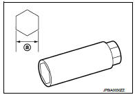
4. Remove spark plug with a spark plug wrench (commercial service tool).
a : 14 mm (0.55 in)
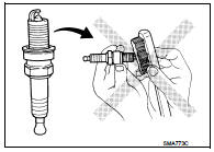
CAUTION:
Never drop or shock spark plug.
INSTALLATION
Install in the reverse order of removal.
Inspection
INSPECTION AFTER REMOVAL
Use the standard type spark plug for normal condition.
Spark plug (Standard type) : Refer to EM-129, "Spark Plug".
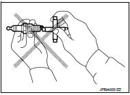
CAUTION:
• Never drop or shock spark plug.
• Never use a wire brush for cleaning.
• If plug tip is covered with carbon, spark plug cleaner may be used.
Cleaner air pressure : Less than 588 kPa (6 kg/cm2,
85 psi)
Cleaning time : Less than 20 seconds
• Spark plug gap adjustment is not required between replacement intervals.
• Measure spark plug gap. when it exceeds the limit, replace spark plug even if it is with in the specified replacement mileage.
Refer to EM-129, "Spark Plug".
 Air cleaner filter
Removal and Installation
REMOVAL
1. Remove air duct assembly (duct side) (1).
2. Unhook the tabs (A) of both ends of the air cleaner cover.
3. Remove the air cleaner filter (1) and air cleaner b ...

Other materials:
Cleaning interior
Occasionally remove loose dust from the interior trim, plastic parts and seats
using a vacuum cleaner or soft bristled brush. Wipe the vinyl and leather surfaces
with a clean, soft cloth dampened in mild soap solution, then wipe clean with a
dry soft cloth.
Regular care and cleaning is requir ...
Steering switch ground circuit
Description
Transmits the steering switch signal to audio unit.
Diagnosis Procedure
1.CHECK STEERING SWITCH SIGNAL GROUND CIRCUIT
1. Disconnect audio unit connector and spiral cable connector.
2. Check continuity between audio unit harness connector and spiral cable
harness connector.
Is t ...
P0487 EGR volume control valve
DTC Logic
DTC DETECTION LOGIC
Diagnosis Procedure
1.CHECK EGR VOLUME CONTROL VALVE CONTROL CIRCUIT
1. Turn ignition switch OFF.
2. Disconnect EGR volume control valve harness connector and ECM harness
connector.
3. Check the continuity between EGR volume control valve terminal harness
co ...
