Nissan Juke Service and Repair Manual : Component parts
Component Parts Location
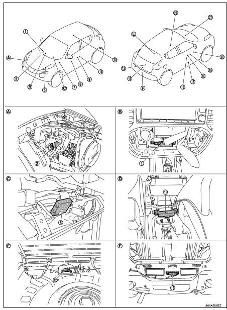
1. Combination meter
2. Intelligent Key warning buzzer
3. Push-button ignition switch
4. Inside key antenna (instrument center)
5. TCM
Refer to TM-133, "CVT CONTROL
SYSTEM : TCM" (RE0F10B models)
or TM-316, "CVT CONTROL SYSTEM
: TCM" (RE0F11A models)
6. Remote keyless entry receiver
7. BCM
Refer to BCS-6, "BODY CONTROL
SYSTEM : Component Parts Location"
8. Power window switch (passenger
side) (door lock and unlock switch)
9. Outside key antenna (passenger side)
10. Front door request switch (passenger
side)
11. Inside key antenna (console)
12. Inside key antenna (luggage room)
13. Back door request switch
14. Back door lock assembly
15. Outside antenna (rear bumper)
16. Front door lock assembly (driver side)
17. Front door switch (driver side)
18. Front door request switch (driver side)
19. Outside key antenna (driver side)
20. Power window main switch (door lock
and unlock switch)
21. Door lock status indicator
22. Air bag diagnosis sensor unit
Refer to SRC-7, "Component Parts Location"
A. View with front bumper removed B. View with multi display unit removed C.
View with instrument panel assembly
removed
D. View with center console assembly removed
E. View with luggage room finisher removed
F. View with rear bumper removed
Component Description
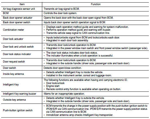
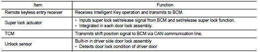

 System (power door lock system)
System Diagram
System Description
DOOR LOCK FUNCTION
Door Lock and Unlock Switch
• The door lock and unlock switch (driver side) is build into power window main
switch.
• The door lock an ...
Other materials:
P0564 ASCD steering switch
DTC Logic
DTC DETECTION LOGIC
Diagnosis Procedure
1.CHECK ASCD STEERING SWITCH CIRCUIT
1. Check ASCD steering switch circuit.
ASCD steering switch>>Refer to EC-1011, "Component Function Check" and EC-1011,
"Diagnosis Procedure".
ASCD main switch>>Refer t ...
Battery charging chart
Slow Charge
1.DETERMINE INITIAL CHARGING CURRENT
1. Determine initial charging current from specific gravity.
2. Check battery type and determine the specified current using the table.
NOTE:
After starting charging, adjustment of charging current is not necessary.
Initial Charging Current ...
Symptom diagnosis
Squeak and rattle trouble diagnoses
Work Flow
CUSTOMER INTERVIEW
Interview the customer if possible, to determine the conditions that exist
when the noise occurs. Use the Diagnostic
Worksheet during the interview to document the facts and conditions when the
noise occurs and any of
the cu ...
