Nissan Juke Service and Repair Manual : Removal and Installation
REMOVAL
1. Remove rear propeller shaft assembly. Refer to DLN-121, "Removal and Installation".
2. Remove rear drive shaft. Refer to RAX-17, "Removal and Installation".
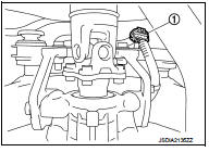
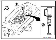
3. Disconnect sub-harness connector (1).
4. Remove rear final drive breather hose.
5. Support rear final drive assembly with a suitable jack.
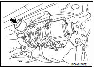
6. Remove rear final drive mounting bolt (
) at rear suspension
member.
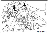
7. Remove final drive mounting bolts and nuts (
), and then
remove rear final drive assembly from final drive mounting
bracket.
CAUTION:
Secure final drive assembly to a suitable jack while removing
it.
8. Remove fuel tank. Refer to FL-23, "4WD : Removal and Installation".
9. Remove final drive mounting bracket.
INSTALLATION
Note the following, and install in the reverse order of removal.
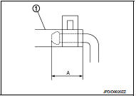
• Install the breather hose (1) to breather tube until dimension (A) shown as follows.
A:
Final drive side : 20mm (0.79 in)
Breather side : 20mm (0.79 in)
CAUTION:
• Never reuse hose clamps.
• Install the hose clamps, with the tab facing vehicle rear.
• If remove breather hose, install breather hose (1) as shown in the figure.
Vehicle front
- Install breather hose with paint mark (A) facing vehicle rear.
• When oil leaks while removing final drive assembly, check oil level after the installation. Refer to DLN-132, "Inspection".
• When replacing rear final drive assembly, perform writing unit parameter. Refer to DLN-39, "Work Procedure".
 Exploded View
1. Final drive mounting bracket
2. Washer
3. Rear final drive assembly
: Vehicle front
: N·m (kg-m, ft-lb)
: Never reuse parts
: Apply multi purpose grease
: Apply gear oil.
...

Other materials:
P0713 transmission fluid temperature sensor A
DTC Logic
DTC CONFIRMATION PROCEDURE
1.PREPARATION BEFORE WORK
If another "DTC CONFIRMATION PROCEDURE" occurs just before, turn ignition
switch OFF and wait for at
least 10 seconds, then perform the next test.
>> GO TO 2.
2.PERFORM DTC CONFIRMATION PROCEDURE
1. Start the ...
Service data and specifications (SDS)
General Specifications
MR16DDT
HR16DE, K9K
Brake Pedal
Brake Booster
2WD
4WD
Front Disc Brake
MR16DDT
HR16DE, K9K
Rear Disc Brake
...
Rear seat (4WD)
Exploded View
1. Seatback board RH
2. Headrest
3. Headrest holder (locked)
4. Headrest holder (free)
5. Seatback trim RH
6. Seatback pad RH
7. Seatback lock knob
8. Seatback lock knob finisher
9. Seatback lock assembly RH
10. Seat lock cover RH
11. Bush
12. Side hinge
13. Spac ...
