Nissan Juke Service and Repair Manual : Periodic maintenance
GEAR OIL
Inspection
OIL LEAKAGE
Make sure that gear oil is not leaking from transaxle or around it.
OIL LEVEL
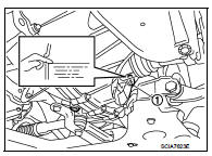
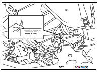
1. Remove filler plug (1) and gasket from transaxle case.
2. Check the oil level from filler plug mounting hole as shown in the figure.
CAUTION:
Never start engine while checking oil level.
3. Set a gasket on filler plug and then install it to transaxle case.
CAUTION:
Never reuse gasket.
4. Tighten filler plug to the specified torque. Refer to TM-88, "Exploded View".
Draining
1. Start engine and let it run to warm up transaxle.
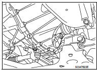
2. Stop engine. Remove drain plug (1) and gasket, using a socket [Commercial service tool] and then drain gear oil.
3. Set a gasket on drain plug and install it to clutch housing, using a socket [Commercial service tool].
CAUTION:
Never reuse gasket.
4. Tighten drain plug to the specified torque. Refer to TM-88, "Exploded View".
Refilling
1. Remove filler plug (1) and gasket from transaxle case.
2. Fill with new gear oil until oil level reaches the specified limit at filler plug mounting hole as shown in the figure.
Oil grade and viscosity : Refer to MA-13, "Fluids and Lubricants".
Oil capacity : Refer to TM-123, "General Specifications".
3. After refilling gear oil, check the oil level. Refer to TM-75, "Inspection".
4. Set a gasket on filler plug and then install it to transaxle case.
CAUTION:
Never reuse gasket.
5. Tighten filler plug to the specified torque. Refer to TM-88, "Exploded View".
 Symptom diagnosis
NOISE, VIBRATION AND HARSHNESS (NVH) TROUBLESHOOTING
NVH Troubleshooting Chart
Use the chart below to find the cause of the symptom. The numbers indicate
the order of the inspection. If necessary, ...

Other materials:
Power supply and ground circuit
MULTI DISPLAY UNIT
MULTI DISPLAY UNIT : Diagnosis Procedure
1.CHECK FUSES
Check if any of the following fuses are blown:
Is the check result normal?
YES >> GO TO 2.
NO >> Replace fuse with a new one after repairing the applicable circuit.
2.CHECK POWER SUPPLY CIRCUIT
Check ...
Hazard warning flasher switch
Activate the hazard warning flasher switch to alert other motorists when you are required to stop or park your Nissan Leaf under emergency conditions. Once engaged, all exterior turn signal lamps will flash simultaneously, providing high visibility to surrounding traffic.
...
Vehicle information
BODY EXTERIOR PAINT COLOR
Body Exterior Paint Color
FOR 2WD MODELS
NOTE:
• S: Solid
• 2S: Solid + Clear
• CS: Color clear solid
• M: Metallic
• P: 2-Coat pearl
• 3P: 3-Coat pearl
• FPM: Iron oxide pearl
• RPM: Multi flex color
• TM: Micro titanium metallic
• PM: ...
