Nissan Juke Service and Repair Manual : P2127, P2128 APP sensor
DTC Logic
DTC DETECTION LOGIC
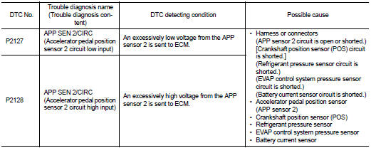
DTC CONFIRMATION PROCEDURE
1.PRECONDITIONING
If DTC Confirmation Procedure has been previously conducted, always perform the following procedure before conducting the next test.
1. Turn ignition switch OFF and wait at least 10 seconds.
2. Turn ignition switch ON.
3. Turn ignition switch OFF and wait at least 10 seconds.
TESTING CONDITION:
Before performing the following procedure, confirm that battery voltage is more
than 8 V at idle.
>> GO TO 2.
2.PERFORM DTC CONFIRMATION PROCEDURE
1. Start engine and let it idle for 1 second.
2. Check DTC.
Is DTC detected? YES >> Proceed to EC-388, "Diagnosis Procedure".
NO >> INSPECTION END
Diagnosis Procedure
1.CHECK APP SENSOR 2 POWER SUPPLY
1. Turn ignition switch OFF.
2. Disconnect accelerator pedal position (APP) sensor harness connector.
3. Turn ignition switch ON.
4. Check the voltage between APP sensor harness connector and ground.
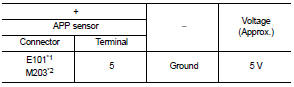
*1: LHD models or RHD with CVT models *2: RHD with M/T models
Is the inspection result normal? YES >> GO TO 3.
NO >> GO TO 2.
2.CHECK SENSOR POWER SUPPLY CIRCUIT
1. Turn ignition switch OFF.
2. Disconnect ECM harness connector.
3. Check harness connector for short to power and short to ground, between the following terminals.
*1: LHD models or RHD with CVT models *2: RHD with M/T models
Is inspection result normal? YES >> Perform the trouble diagnosis for power supply circuit.
NO >> Repair or replace error-detected parts.
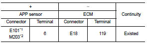
3.CHECK APP SENSOR 2 GROUND CIRCUIT
1. Turn ignition switch OFF.
2. Disconnect ECM harness connector.
3. Check the continuity between APP sensor harness connector and ECM harness connector.
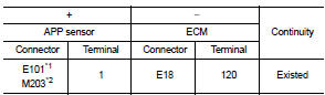
*1: LHD models or RHD with CVT models *2: RHD with M/T models
4. Also check harness for short to power.
Is the inspection result normal? YES >> GO TO 4.
NO >> Repair or replace error-detected parts.
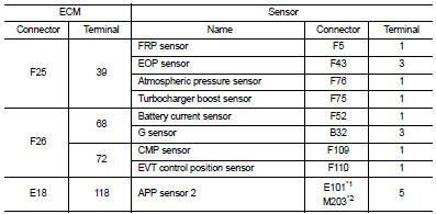
4.CHECK APP SENSOR 2 INPUT SIGNAL CIRCUIT
1. Check the continuity between APP sensor harness connector and ECM harness connector.
*1: LHD models or RHD with CVT models *2: RHD with M/T models
2. Also check harness for short to ground and to power.
Is the inspection result normal? YES >> GO TO 5.
NO >> Repair or replace error-detected parts 5.CHECK APP SENSOR
Check the APP sensor. Refer to EC-390, "Component Inspection".
Is the inspection result normal? YES >> Check intermittent incident. Refer to GI-42, "Intermittent Incident".
NO >> Replace accelerator pedal assembly. Refer to EM-28, "Exploded View".
Component Inspection
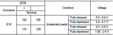
1.CHECK ACCELERATOR PEDAL POSITION SENSOR
1. Turn ignition switch OFF.
2. Reconnect all harness connectors disconnected.
3. Turn ignition switch ON.
4. Check the voltage between ECM harness connector terminals as per the following condition.
Is the inspection result normal? YES >> INSPECTION END
NO >> Replace accelerator pedal assembly. Refer to EM-28, "Exploded View".
 P2122, P2123 APP sensor
DTC Logic
DTC DETECTION LOGIC
NOTE:
If DTC P2122 or P2123 is displayed with DTC P0643, first perform the trouble
diagnosis for DTC P0643.
Refer to EC-307, "DTC Logic".
DTC CONFIRM ...
 P2135 TP sensor
DTC Logic
DTC DETECTION LOGIC
NOTE:
If DTC P2135 is displayed with DTC P0643, first perform the trouble diagnosis
for DTC P0643. Refer to
EC-307, "DTC Logic".
DTC CONFIRMATION PROCE ...
Other materials:
Diagnosis system (ECM)
Diagnosis description : 1st Trip Detection Logic and Two Trip Detection
Logic
When a malfunction is detected for the first time, 1st trip DTC and 1st trip
Freeze Frame data are stored in the
ECM memory. The MI will not illuminate at this stage. <1st trip>
If the same malfunction is dete ...
Front fog lamp
Exploded View
1. Front fog lamp assembly
2. Metal clip
3. Front fog lamp bulb
4. Front fog lamp bracket
5. U nut
6. Front bumper fascia lower
: Pawl
: N·m (kg-m, in-lb)
Removal and Installation
CAUTION:
Disconnect the battery negative terminal or remove the fuse.
REMOVAL
1. Remov ...
Door motor
Exploded View
LEFT SIDE
1. A/C unit assembly
2. Intake door lever
3. Intake door link
4. Intake door motor
5. Air mix door motor
6. Air mix door link
7. Max. cool door
8. Upper air mix door lever
9. Air mix door rod
10. Lower air mix door lever
RIGHT SIDE
1. A/C unit assembly ...
