Nissan Juke Service and Repair Manual : P1615 diffrence of key
DTC Logic
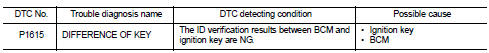
DTC DETECTION LOGIC
DTC CONFIRMATION PROCEDURE
1.PERFORM DTC CONFIRMATION PROCEDURE
1. Turn ignition switch ON.
2. Check DTC in ÔÇťSelf Diagnostic ResultÔÇŁ mode of ÔÇťENGINEÔÇŁ using CONSULT-III.
Is DTC detected? YES >> Refer to SEC-198, "Diagnosis Procedure".
NO >> INSPECTION END
Diagnosis Procedure
1.PERFORM INITIALIZATION
Perform initialization of BCM and reregistration of all ignition keys using CONSULT-III.
For initialization and registration procedures, refer to CONSULT-III Operation Manual NATS-IVIS/NVIS.
Can the system be initialized and can the engine be started with reregistered ignition key? YES >> INSPECTION END
NO >> GO TO 2.
2.REPLACE IGNITION KEY
1. Replace ignition key.
2. Perform initialization of BCM and reregistration of all ignition keys using CONSULT-III.
For initialization and registration procedures, refer to CONSULT-III Operation Manual NATS-IVIS/NVIS.
Can the system be initialized and can the engine be started with reregistered ignition key? YES >> INSPECTION END
NO >> GO TO 3.
3.REPLACE BCM
1. Replace BCM. Refer to BCS-161, "Removal and Installation".
2. Perform initialization of BCM and reregistration of all ignition keys using CONSULT-III.
For initialization and registration procedures, refer to CONSULT-III Operation Manual NATS-IVIS/NVIS.
>> INSPECTION END
 P1614 chain of IMMU-KEY
DTC Logic
DTC DETECTION LOGIC
DTC CONFIRMATION PROCEDURE
1.PERFORM DTC CONFIRMATION PROCEDURE
1. Turn ignition switch ON.
2. Check DTC in ÔÇťSelf Diagnostic ResultÔÇŁ mode of ÔÇťENGINEÔÇŁ using ...
 P1616 ECM
DTC Logic
DTC DETECTION LOGIC
DTC CONFIRMATION PROCEDURE
1.PERFORM DTC CONFIRMATION PROCEDURE FOR MALFUNCTION
1. Turn ignition switch ON amd wait 2 seconds or more.
2. Check DTC in ÔÇťSelf Diag ...
Other materials:
Brake pad wear warning
The disc brake pads have audible wear warnings.
When a brake pad requires replacement, it will make a high pitched scraping sound
when the vehicle is in motion. This scraping sound will first occur only when the
brake pedal is depressed. After more wear of the brake pad, the sound will always
...
Brake booster
Exploded View
2WD
MR16DDT, HR16DE
1. Master cylinder assembly
2. Vacuum pipe
3. Brake booster
4. Lock nut
5. Clevis
6. Gasket
: N┬Ěm (kg-m, ft-lb)
K9K
1. Master cylinder assembly
2. Vacuum pipe
3. Brake booster
4. Lock nut
5. Clevis
6. Gasket
: N┬Ěm (kg-m, ft-lb)
4WD
...
System
ENGINE CONTROL SYSTEM : System Diagram
1. Priming pump
2. Fuel filter
3. High pressure supply pump
4. High pressure supply pump (internal
transfer pump)
5. High pressure supply pump (volumetric
control valve)
6. High pressure supply pump (high
pressure pump)
7. High pressure supply pum ...
