Nissan Juke Service and Repair Manual : P1614 chain of IMMU-KEY
DTC Logic
DTC DETECTION LOGIC
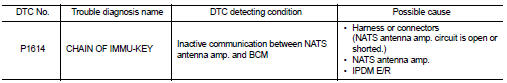
DTC CONFIRMATION PROCEDURE
1.PERFORM DTC CONFIRMATION PROCEDURE 1
1. Contact Intelligent Key backside to push-button ignition switch.
2. Check DTC in “Self Diagnostic Result” mode of “ENGINE” using CONSULT-III.
Is DTC detected? YES >> Go to SEC-55, "Diagnosis Procedure".
NO >> GO TO 2.
2.PERFORM DTC CONFIRMATION PROCEDURE 2
1. Press the push-button ignition switch.
2. Check DTC in “Self Diagnostic Result” mode of “ENGINE” using CONSULT-III.
Is DTC detected? YES >> Go to SEC-55, "Diagnosis Procedure".
NO >> INSPECTION END
Diagnosis Procedure
1.CHECK FUSE
1. Turn ignition switch OFF.
2. Check that the following fuse in IPDM E/R is not blown.

Is the fuse fusing? YES >> Replace the blown fuse after repairing the cause of blowing.
NO >> GO TO 2.
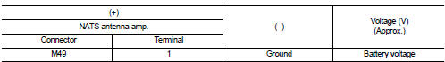
2.CHECK NATS ANTENNA AMP. POWER SUPPLY
1. Disconnect NATS antenna amp. connector.
2. Check voltage between NATS antenna amp. harness connector and ground.
Is the inspection result normal? YES >> GO TO 4.
NO >> GO TO 3.
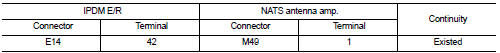
3.CHECK NATS ANTENNA AMP. POWER SUPPLY CIRCUIT
1. Disconnect IPDM E/R connector.
2. Check continuity between IPDM E/R harness connector and NATS antenna amp. connector
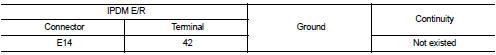
3. Check continuity between IPDM E/R harness connector and ground.
the inspection result normal? YES >> Replace IPDM E/R. Refer to PCS-34, "Removal and Installation".
NO >> Repair or replace harness.
4.CHECK NATS ANTENNA AMP. OUTPUT SIGNAL 1
1. Connect NATS antenna amp. connector.
2. Disconnect BCM connector.
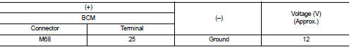
3. Check voltage between BCM harness connector and ground.
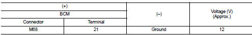
Is the inspection result normal? YES >> GO TO 6.
NO >> GO TO 5.
5.CHECK NATS ANTENNA AMP. OUTPUT SIGNAL CIRCUIT 1
1. Disconnect NATS antenna amp. connector.
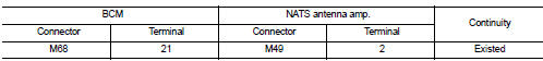
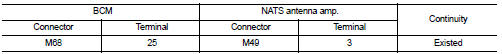
2. Check continuity between BCM harness connector and NATS antenna amp. connector.
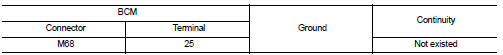
3. Check continuity between BCM harness connector and ground.
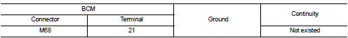
Is the inspection result normal? YES >> Replace NATS antenna amp. Refer to SEC-167, "Removal and Installation".
NO >> Repair or replace harness.
6.CHECK NATS ANTENNA AMP. COMMUNICATION SIGNAL 1
1. Connect BCM connector.
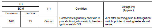
2. Check voltage between BCM harness connector and ground using analog tester.
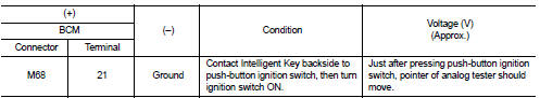
Is the inspection result normal?
YES >> GO TO 7.
NO >> Replace NATS antenna amp. Refer to SEC-167, "Removal and Installation".
7.CHECK NATS ANTENNA AMP. OUTPUT SIGNAL 2
1. Disconnect BCM connector.
2. Check voltage between BCM harness connector and ground.
Is the inspection result normal? YES >> GO TO 9.
NO >> GO TO 8.
8.CHECK NATS ANTENNA AMP. OUTPUT SIGNAL CIRCUIT 2
1. Disconnect NATS antenna amp. connector.
2. Check continuity between BCM harness connector and NATS antenna amp. connector.
3. Check continuity between BCM harness connector and ground.
Is the inspection result normal? YES >> Replace NATS antenna amp. Refer to SEC-167, "Removal and Installation".
NO >> Repair or replace harness.
9.CHECK NATS ANTENNA AMP. COMMUNICATION SIGNAL 2
1. Connect BCM connector.
2. Check voltage between BCM harness connector and ground using analog tester.
Is the inspection result normal? YES >> GO TO 10.
NO >> Replace NATS antenna amp. Refer to SEC-167, "Removal and Installation".
10.CHECK NATS ANTENNA AMP. GROUND CIRCUIT
1. Disconnect NATS antenna amp. connector.
2. Check continuity between NATS antenna amp. harness connector and ground.

Is the inspection result normal?
YES >> GO TO 11.
NO >> Repair or replace harness.
11.CHECK INTERMITTENT INCIDENT
Refer to GI-42, "Intermittent Incident".
>> INSPECTION END
 P1612 chain of ECM-IMMU
DTC Logic
DTC DETECTION LOGIC
NOTE:
• If DTC P1612 is displayed with DTC U1000 (for BCM), first perform the trouble
diagnosis for DTC U1000.
Refer to BCS-83, "DTC Logic".
• If ...
 P1616 ECM
DTC Logic
DTC DETECTION LOGIC
DTC CONFIRMATION PROCEDURE
1.PERFORM DTC CONFIRMATION PROCEDURE FOR MALFUNCTION
1. Turn ignition switch ON amd wait 2 seconds or more.
2. Check DTC in “Self Diag ...
Other materials:
Map light control switch (if so equipped)
The map lights control switch has three positions: ON1 , OFF2 and center.
ON position
When the switch is in the ON position 1 , the map lights will illuminate.
OFF position
When the switch is in the OFF position2 , the map lights will not illuminate,
regardless of the condition.
Center posi ...
P1641 thermoplunger control unit
DTC Logic
DTC DETECTION LOGIC
Diagnosis Procedure
1.CHECK THERMOPLUNGER CONTROL UNIT POWER SUPPLY CIRCUIT
1. Turn ignition switch OFF.
2. Disconnect thermoplunger control unit harness connector.
3. Check the voltage between thermoplunger control unit harness connector and
ground.
Is the ...
P0730 incorrect gear ratio
Description
TCM selects the gear ratio using the engine load (throttle position), the
primary pulley revolution speed, and
the secondary pulley revolution speed as input signal. Then it changes the
operating pressure of the primary
pulley and the secondary pulley and changes the groove width ...
