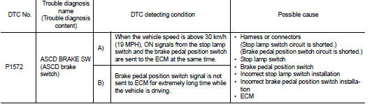
Nissan Juke Service and Repair Manual : P1572 ASCD brake switch
DTC Logic
DTC DETECTION LOGIC
NO
TE:
• If DTC P1572 is displayed with DTC P0605, first perform the trouble diagnosis
for DTC P0605. Refer
to EC-302, "DTC Logic".
• This self-diagnosis has the one trip detection logic. When malfunction A is detected, DTC is not stored in ECM memory. And in that case, 1st trip DTC and 1st trip freeze frame data are displayed.
1st trip DTC is erased when ignition switch OFF. And even when malfunction A is detected in two consecutive trips, DTC is not stored in ECM memory.
DTC CONFIRMATION PROCEDURE
1.PRECONDITIONING
If DTC Confirmation Procedure has been previously conducted, always perform the following procedure before conducting the next test.
1. Turn ignition switch OFF and wait at least 10 seconds.
2. Turn ignition switch ON.
3. Turn ignition switch OFF and wait at least 10 seconds.
NOTE
:
Procedure for malfunction B is not described here. It takes extremely long time
to complete procedure for malfunction
B. By performing procedure for malfunction A, the incident that causes
malfunction B can be
detected.
>> GO TO 2.
2.PERFORM DTC CONFIRMATION PROCEDURE FOR MALFUNCTION A
1. Start engine.
2. Press MAIN switch and make sure that CRUISE indicator is displayed in combination meter.
3. Drive the vehicle for at least 5 consecutive seconds as per the following conditions.
CAUTION:
Always drive vehicle at a safe speed.
NOTE:
This procedure may be conducted with the drive wheels lifted in the shop or by driving the vehicle.
If a road test is expected to be easier, it is unnecessary to lift the vehicle.
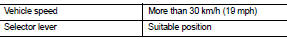
4. Check DTC.
Is DTC detected? YES >> Proceed to EC-352, "Diagnosis Procedure".
NO >> GO TO 3.
3.PERFORM DTC CONFIRMATION PROCEDURE FOR MALFUNCTION B
1. Drive the vehicle for at least 5 consecutive seconds as per the following conditions.
CAUTION:
Always drive vehicle at a safe speed.
NOTE
:
This procedure may be conducted with the drive wheels lifted in the shop or by
driving the vehicle.
If a road test is expected to be easier, it is unnecessary to lift the vehicle.
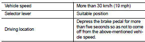
2. Check DTC.
Is DTC detected? YES >> Proceed to EC-352, "Diagnosis Procedure".
NO >> INSPECTION END
Diagnosis Procedure
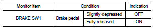
1.CHECK OVERALL FUNCTION-I
 With CONSULT-III
1. Turn ignition switch ON.
2. Select “BRAKE SW1” in “DATA MONITOR” mode of “ENGINE” using CONSULT-III.
3. Check “BRAKE SW1” indication as per the following conditions.
 Without CONSULT-III
1. Turn ignition switch ON.
2. Check the voltage between ECM harness connector terminals as per the following.
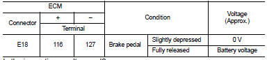
Is the inspection result normal? YES >> GO TO 2.
NO >> GO TO 3.
2.CHECK OVERALL FUNCTION-II
 With CONSULT-III
Select “BRAKE SW2” and check indication as per the following conditions.
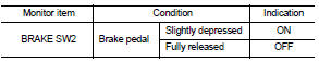
 Without CONSULT-III
Check the voltage between ECM harness connector terminals as per the following conditions.
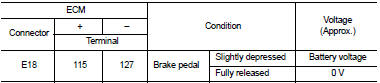
Is the inspection result normal? YES >> Check intermittent incident. Refer to GI-42, "Intermittent Incident".
NO >> GO TO 6.
3.CHECK BRAKE PEDAL POSITION SWITCH POWER SUPPLY
1. Turn ignition switch OFF.
2. Disconnect brake pedal position switch harness connector.
3. Turn ignition switch ON.
4. Check the voltage between brake pedal position switch harness connector and ground.
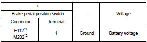
*1: LHD models or RHD with CVT models *2: RHD with M/T models
Is the inspection result normal? YES >> GO TO 4.
NO >> Perform the trouble diagnosis for power supply circuit.
4.CHECK BRAKE PEDAL POSITION SWITCH INPUT SIGNAL CIRCUIT
1. Turn ignition switch OFF.
2. Disconnect ECM harness connector.
3. Check the continuity between brake pedal position switch harness connector and ECM harness connector.
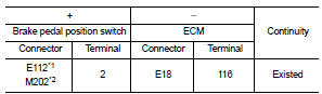
*1: LHD models or RHD with CVT models *2: RHD with M/T models
4. Also check harness for short to ground and to power.
Is the inspection result normal? YES >> GO TO 5.
NO >> Repair or replace error-detected parts.
5.CHECK BRAKE PEDAL POSITION SWITCH
Check the brake pedal position switch. Refer to EC-426, "Component Inspection (Brake Pedal Position Switch)" Is the inspection result normal? YES >> Check intermittent incident. Refer to GI-42, "Intermittent Incident".
NO >> Replace brake pedal position switch. Refer to BR-20, "Exploded View" (LHD) or BR-88, "Exploded View" (RHD).
6.CHECK STOP LAMP SWITCH POWER SUPPLY CIRCUIT
1. Turn ignition switch OFF.
2. Disconnect stop lamp switch harness connector.
3. Check the voltage between stop lamp switch harness connector and ground.
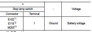
*1: CVT models
*2: LHD with M/T models
*3: RHD with M/T models
Is the inspection result normal? YES >> GO TO 7.
NO >> Perform the trouble diagnosis for power supply circuit.
7.CHECK STOP LAMP SWITCH INPUT SIGNAL CIRCUIT
1. Disconnect ECM harness connector.
2. Check the continuity between stop lamp switch harness connector and ECM harness connector.
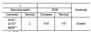
*1: CVT models
*2: LHD with M/T models
*3: RHD with M/T models
3. Also check harness for short to ground and to power.
Is the inspection result normal? YES >> GO TO 8.
NO >> Repair or replace error-detected parts.
8.CHECK STOP LAMP SWITCH
Check the stop lamp switch. Refer to EC-350, "Component Inspection (Stop Lamp Switch)".
Is the inspection result normal? YES >> Check intermittent incident. Refer to GI-42, "Intermittent Incident".
NO >> Replace stop lamp switch. Refer to BR-20, "Exploded View" (LHD) or BR-88, "Exploded View" (RHD).
Component Inspection (Brake Pedal Position Switch)
1.CHECK BRAKE PEDAL POSITION SWITCH-I
1. Turn ignition switch OFF.
2. Disconnect brake pedal position harness connector.
3. Check the continuity between brake pedal position switch terminals as per the following conditions.
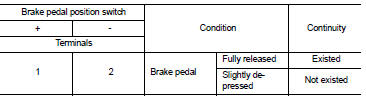
Is the inspection result normal? YES >> INSPECTION END NO >> GO TO 2.
2.CHECK BRAKE PEDAL POSITION SWITCH-II
1. Adjust brake pedal position switch installation. Refer to BR-9, "Inspection and Adjustment" (LHD) or BR- 77, "Inspection and Adjustment" (RHD).
2. Check the continuity between brake pedal position switch terminals as per the following conditions.
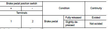
Is the inspection result normal? YES >> INSPECTION END
NO >> Replace brake pedal position switch. Refer to BR-20, "Exploded View" (LHD) or BR-88, "Exploded View" (RHD).
Component Inspection (Stop Lamp Switch)
1.CHECK STOP LAMP SWITCH-I
1. Turn ignition switch OFF.
2. Disconnect stop lamp switch harness connector.
3. Check the continuity between stop lamp switch terminals as per the following conditions.
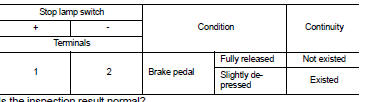
Is the inspection result normal? YES >> INSPECTION END
NO >> GO TO 2.
2.CHECK STOP LAMP SWITCH-II
1. Adjust stop lamp switch installation. Refer to BR-9, "Inspection and Adjustment" (LHD) or BR-77, "Inspection and Adjustment" (RHD).
2. Check the continuity between stop lamp switch terminals as per the following conditions.
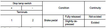
Is the inspection result normal? YES >> INSPECTION END NO >> Replace stop lamp switch. Refer to BR-20, "Exploded View" (LHD) or BR-88, "Exploded View" (RHD).
 P1564 ASCD steering switch
DTC Logic
DTC DETECTION LOGIC
NOTE:
If DTC P1564 is displayed with DTC P0605, first perform the trouble diagnosis
for DTC P0605. Refer to
EC-302, "DTC Logic".
DTC CONFIRMATION PROCE ...
 P1574 ASCD vehicle speed sensor
Description
The ECM receives two vehicle speed sensor signals via CAN communication line.
One is sent from combination
meter, and the other is from TCM (Transmission control module). The ECM uses ...
Other materials:
P1745 line pressure control
Description
The line pressure solenoid valve regulates the oil pump discharge pressure to
suit the driving condition in
response to a signal sent from the TCM.
DTC Logic
DTC DETECTION LOGIC
DTC CONFIRMATION PROCEDURE
NOTE:
If “DTC CONFIRMATION PROCEDURE” has been previously performed, ...
P17BB primary pressure solenoid
DTC Logic
DTC DETECTION LOGIC
DTC CONFIRMATION PROCEDURE
1.PREPARATION BEFORE WORK
If another "DTC CONFIRMATION PROCEDURE" occurs just before, turn ignition
switch OFF and wait for at
least 10 seconds, then perform the next test.
>> GO TO 2.
2.CHECK DTC DETECTION
1. S ...
Rear wheel hub and housing
Inspection
COMPONENT PART
Check the mounting conditions (looseness, back lash) of each component and
component conditions (wear,
damage) are normal.
WHEEL HUB ASSEMBLY (BEARING-INTEGRATED TYPE)
Check the following items, and replace the part it necessary.
• Move wheel hub assembly in t ...
