Nissan Juke Service and Repair Manual : P1564 ASCD steering switch
DTC Logic
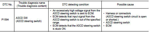
DTC DETECTION LOGIC
NOTE
:
If DTC P1564 is displayed with DTC P0605, first perform the trouble diagnosis
for DTC P0605. Refer to
EC-302, "DTC Logic".
DTC CONFIRMATION PROCEDURE
1.PRECONDITIONING
If DTC Confirmation Procedure has been previously conducted, always perform the following procedure before conducting the next test.
1. Turn ignition switch OFF and wait at least 10 seconds.
2. Turn ignition switch ON.
3. Turn ignition switch OFF and wait at least 10 seconds.
>> GO TO 2.
2.PERFORM DTC CONFIRMATION PROCEDURE
1. Turn ignition switch ON.
2. Wait at least 10 seconds.
3. Press MAIN switch for at least 10 seconds, then release it and wait at least 10 seconds.
4. Press CANCEL switch for at least 10 seconds, then release it and wait at least 10 seconds.
5. Press RES/+ switch for at least 10 seconds, then release it and wait at least 10 seconds.
6. Press SET/− switch for at least 10 seconds, then release it and wait at least 10 seconds.
7. Check DTC.
Is DTC detected? YES >> Proceed to EC-343, "Diagnosis Procedure".
NO >> INSPECTION END
Diagnosis Procedure
1.CHECK ASCD STEERING SWITCH CIRCUIT
 With CONSULT-III
1. Turn ignition switch ON.
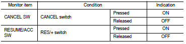
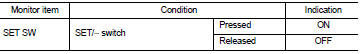
2. Select “CANCEL SW”, “RESUME/ACC SW” and “SET SW” in “DATA MONITOR” mode of “ENGINE” using CONSULT-III.
3. Check each item indication as per the following conditions.
 Without CONSULT-III
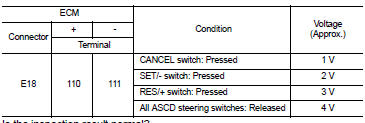
1. Turn ignition switch ON.
2. Check the voltage between ECM harness connector terminals.
Is the inspection result normal? YES >> Check intermittent incident. Refer to GI-42, "Intermittent Incident".
NO >> GO TO 2.
2.CHECK ASCD STEERING SWITCH GROUND CIRCUIT
1. Turn ignition switch OFF.
2. Disconnect ECM harness connector.
3. Disconnect combination switch (spiral cable) harness connector.
4. Check the continuity between combination switch (spiral cable) and ECM harness connector.
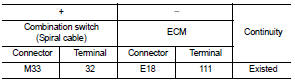
5. Also check harness for short to ground and to power.
Is the inspection result normal? YES >> GO TO 3.
NO >> Repair or replace error-detected parts.
3.CHECK ASCD STEERING SWITCH INPUT SIGNAL CIRCUIT
1. Check the continuity between ECM harness connector and combination switch.
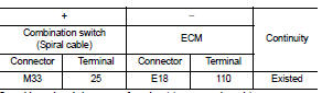
2. Also check harness for short to ground and to power.
Is the inspection result normal? YES >> GO TO 4.
NO >> Repair or replace error-detected parts.
4.CHECK ASCD STEERING SWITCH
Refer to EC-345, "Component Inspection".
Is the inspection result normal?
YES >> Check intermittent incident. Refer to GI-42, "Intermittent Incident".
NO >> Replace ASCD steering switch. Refer to ST-9, "Exploded View".
Component Inspection
1.CHECK ASCD STEERING SWITCH-I
1. Disconnect combination switch (spiral cable) harness connector.
2. Check the continuity between combination switch harness connector terminals as per the following conditions.
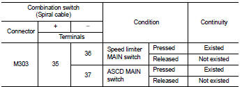
Is the inspection result normal? YES >> INSPECTION END
NO >> Replace ASCD steering switch. Refer to ST-9, "Exploded View".
2.CHECK ASCD STEERING SWITCH
1. Disconnect combination switch (spiral cable) harness connector.
2. Check the resistance between combination switch harness connector terminals as per the following conditions.
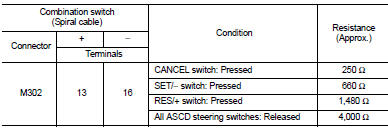
Is the inspection result normal? YES >> INSPECTION END NO >> Replace ASCD steering switch. Refer to ST-9, "Exploded View".
 P1556, P1557 battery temperature
sensor
P1556, P1557 battery temperature
sensor
DTC Logic
DTC DETECTION LOGIC
DTC CONFIRMATION PROCEDURE
1.PRECONDITIONING
1. Turn ignition switch OFF and wait at lest 10 seconds.
2. Turn ignition switch ON.
3. Turn ignition switch OFF and ...
 P1572 ASCD brake switch
DTC Logic
DTC DETECTION LOGIC
NOTE:
• If DTC P1572 is displayed with DTC P0605, first perform the trouble diagnosis
for DTC P0605. Refer
to EC-302, "DTC Logic".
• This self-diagno ...
Other materials:
Rear door lock
Exploded View
1. Outside handle assembly
2. Inside handle
3. TORX bolt
4. Door lock assembly
5. Rear door sealing screen
: Clip
: Pawl
: Vehicle front
: Do not reuse
: N·m (kg-m, in-lb)
: Body grease
Door lock
DOOR LOCK : Removal and Installation
REMOVAL
1. Remove rear door glas ...
B2630, B2631 sunload sensor
DTC Logic
DTC DETECTION LOGIC
NOTE:
• If DTC is displayed along with DTC U1000, first perform the trouble diagnosis
for DTC U1000. Refer to HAC-
141, "DTC Logic".
• If DTC is displayed along with DTC U1010, first perform the trouble diagnosis
for DTC U1010. HAC-142,
"D ...
P0237, P0238 TC boost sensor
DTC Logic
DTC DETECTION LOGIC
DTC CONFIRMATION PROCEDURE
1.PRECONDITIONING
If DTC Confirmation Procedure has been previously conducted, always perform
the following procedure
before conducting the next test.
1. Turn ignition switch OFF and wait at least 10 seconds.
2. Turn ignition swit ...
