Nissan Juke Service and Repair Manual : P1556, P1557 battery temperature sensor
DTC Logic
DTC DETECTION LOGIC
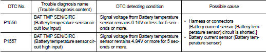
DTC CONFIRMATION PROCEDURE
1.PRECONDITIONING
1. Turn ignition switch OFF and wait at lest 10 seconds.
2. Turn ignition switch ON.
3. Turn ignition switch OFF and wait at least 10 seconds.
TESTING CONDITION:
Before performing the following procedure, confirm that battery voltage is 10 V
or more at idle.
>> GO TO 2.
2.PERFORM DTC CONFIRMATION PROCEDURE
1. Start the engine and let it idle at least 10 seconds.
2. Check 1st trip DTC.
Is 1st trip DTC detected? YES >> Proceed to EC-341, "Diagnosis Procedure".
NO >> INSPECTION END
Diagnosis Procedure
1.CHECK BATTERY TEMPERATURE SENSOR POWER SUPPLY
1. Turn ignition switch OFF.
2. Disconnect battery current sensor harness connector.
3. Turn ignition switch ON.
4. Check the voltage between battery current sensor harness connector and ground.
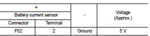
Is the inspection result normal? YES >> GO TO 3.
NO >> GO TO 2.
2.CHECK BATTERY TEMPERATURE SENSOR POWER SUPPLY CIRCUIT
1. Turn ignition switch OFF.
2. Disconnect ECM harness connector.
3. Check the continuity between battery current sensor harness connector and ECM harness connector.
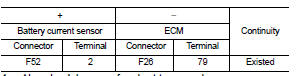
4. Also check harness for short to ground.
Is the inspection result normal? YES >> Perform the trouble diagnosis for power supply circuit.
NO >> Repair or replace error-detected parts.
3.CHECK BATTERY TEMPERATURE SENSOR GROUND CIRCUIT
1. Turn ignition switch OFF.
2. Disconnect ECM harness connector.
3. Check the continuity between battery current sensor harness connector and ECM harness connector.
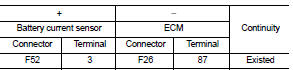
4. Also check harness for short to power.
Is the inspection result normal? YES >> GO TO 4.
NO >> Repair or replace error-detected parts.
4.CHECK BATTERY TEMPERATURE SENSOR
Check the battery temperature sensor. Refer to EC-342, "Component Inspection".
Is the inspection result normal? YES >> Check intermittent incident. Refer to GI-42, "Intermittent Incident".
NO >> Replace battery negative cable assembly. Refer to PG-125, "Exploded View".
Component Inspection
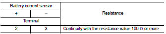
1.CHECK BATTERY TEMPERATURE SENSOR
1. Turn ignition switch OFF.
2. Disconnect battery current sensor.
3. Check the resistance between battery current sensor connector terminals.
Is the inspection result normal? YES >> INSPECTION END
NO >> Replace battery negative cable assembly. Refer to PG-125, "Exploded View".
 P1554 battery current sensor
DTC Logic
DTC DETECTION LOGIC
DTC CONFIRMATION PROCEDURE
1.PERFORM COMPONENT FUNCTION CHECK
Perform component function check. Refer to EC-337, "Component Function
Check".
NOTE:
U ...
 P1564 ASCD steering switch
DTC Logic
DTC DETECTION LOGIC
NOTE:
If DTC P1564 is displayed with DTC P0605, first perform the trouble diagnosis
for DTC P0605. Refer to
EC-302, "DTC Logic".
DTC CONFIRMATION PROCE ...
Other materials:
4WD mode indicator lamp (4WD)
Component Function Check
1.4WD MODE INDICATOR LAMP OPERATION CHECK
Check that 4WD mode indicator lamp (4WD) turns on for approximately 1 second
after the ignition switch is
turned ON.
Is the inspection result normal?
YES >> INSPECTION END
NO >> Proceed to diagnosis procedure. R ...
Intelligent Cruise Control (ICC) (for vehicles with ProPILOT Assist)
WARNING
Failure to strictly adhere to these warnings and operational instructions regarding the Intelligent Cruise Control (ICC) system in your Nissan Leaf could result in a serious accident, personal injury, or death.
The ICC system is strictly a driver-assistance aid; it is not ...
A/C control
Exploded View
1. Intake door cable
2. Mode door cable
3. A/C control
4. Air mix door cable
5. Intake door lever knob
A. To mode door link
B. To intake door link
C. To air mix door link
Removal and Installation
REMOVAL
1. Remove A/C finisher. Refer to IP-13, "Removal and Install ...
