Nissan Juke Service and Repair Manual : P1554 battery current sensor
DTC Logic
DTC DETECTION LOGIC
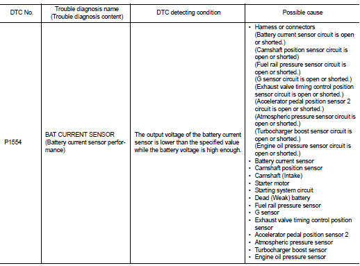
DTC CONFIRMATION PROCEDURE
1.PERFORM COMPONENT FUNCTION CHECK
Perform component function check. Refer to EC-337, "Component Function Check".
NOTE
:
Use component function check to check the overall function of the battery
current sensor circuit. During this
check, a 1st trip DTC might not be confirmed.
Is the inspection result normal? YES >> INSPECTION END
NO >> Proceed to EC-338, "Diagnosis Procedure".
Component Function Check
1.PRECONDITIONING
TESTING CONDITION: • Before performing the following procedure, confirm that battery voltage is more than 12.8 V at idle.
• Before performing the following procedure, confirm that all load switches and A/C switch are turned OFF.
>> GO TO 2.
2.PERFORM COMPONENT FUNCTION CHECK
 With CONSULT-III
1. Start engine and let it idle.
2. Select “BAT CUR SEN” in “DATA MONITOR” mode of “ENGINE” using CONSULT-III.
3. Check “BAT CUR SEN” indication for 10 seconds.
“BAT CUR SEN” should be above 2,300 mV at least once.
 Without CONSULT-III
1. Start engine and let it idle.
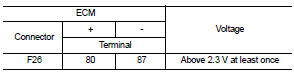
2. Check the voltage between ECM harness connector and ground.
Is the inspection result normal? YES >> INSPECTION END
NO >> Proceed to EC-338, "Diagnosis Procedure".
Diagnosis Procedure
1.CHECK BATTERY CURRENT SENSOR POWER SUPPLY
1. Turn ignition switch OFF.
2. Disconnect battery current sensor harness connector.
3. Turn ignition switch ON.
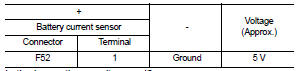
4. Check the voltage between battery current sensor harness connector and ground.
Is the inspection result normal? YES >> GO TO 3.
NO >> GO TO 2.
2.CHECK SENSOR POWER SUPPLY CIRCUIT
1. Turn ignition switch OFF.
2. Disconnect ECM harness connector.
3. Check harness connector for short to power and short to ground, between the following terminals.
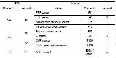
*1: LHD models or RHD with CVT models *2: RHD with M/T models
Is the inspection result normal? YES >> Perform the trouble diagnosis for power supply circuit.
NO >> Repair or replace error-detected parts.
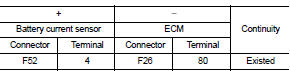
3.CHECK BATTERY CURRENT SENSOR GROUND CIRCUIT
1. Turn ignition switch OFF.
2. Disconnect ECM harness connector.
3. Check the continuity between battery current sensor harness connector and ECM harness connector.
4. Also check harness for short to power.
Is the inspection result normal? YES >> GO TO 4.
NO >> Repair or replace error-detected parts.
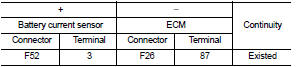
4.CHECK BATTERY CURRENT SENSOR INPUT SIGNAL CIRCUIT
1. Check the continuity between battery current sensor harness connector and ECM harness connector.
2. Also check harness for short to ground and to power.
Is the inspection result normal? YES >> GO TO 5.
NO >> Repair or replace error-detected parts
5.CHECK BATTERY CURRENT SENSOR
Check the battery current sensor. Refer to EC-330, "Component Inspection".
Is the inspection result normal? YES >> Check intermittent incident. Refer to GI-42, "Intermittent Incident".
NO >> Replace battery negative cable assembly. Refer to PG-125, "Exploded View".
Component Inspection
1.CHECK BATTERY CURRENT SENSOR
1. Turn ignition switch OFF.
2. Reconnect harness connectors disconnected.
3. Disconnect battery negative cable.
4. Install jumper cable between battery negative terminal and body ground.
5. Turn ignition switch ON.
6. Check the voltage between ECM harness connector and ground.
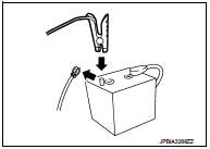
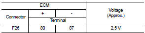
Before measuring the terminal voltage, confirm that the battery is fully charged. Refer to PG-111, "How to Handle Battery".
Is the inspection result normal? YES >> INSPECTION END
NO >> Replace battery negative cable assembly. Refer to PG-125, "Exploded View".
 P1553 battery current sensor
DTC Logic
DTC DETECTION LOGIC
DTC CONFIRMATION PROCEDURE
1.PRECONDITIONING
If DTC Confirmation Procedure has been previously conducted, always perform
the following before conducting
the next ...
 P1556, P1557 battery temperature
sensor
P1556, P1557 battery temperature
sensor
DTC Logic
DTC DETECTION LOGIC
DTC CONFIRMATION PROCEDURE
1.PRECONDITIONING
1. Turn ignition switch OFF and wait at lest 10 seconds.
2. Turn ignition switch ON.
3. Turn ignition switch OFF and ...
Other materials:
Diagnosis system (BCM)
Common item
COMMON ITEM : CONSULT-III Function (BCM - COMMON ITEM)
APPLICATION ITEM
CONSULT-III performs the following functions via CAN communication with BCM.
SYSTEM APPLICATION
BCM can perform the following functions for each system.
NOTE:
It can perform the diagnosis modes except the ...
Additional service when replacing TCM
Description
Always perform the following items when the TCM is replaced.
CHECK LOADING OF CALIBRATION DATA
• The TCM acquires calibration data (individual characteristic value) of each
solenoid that is stored in the
ROM assembly (in the control valve). This enables the TCM to perform accurat ...
Engine idle speed too high
Description
CHART 5: ENGINE IDLE SPEED TOO HIGH
Diagnosis Procedure
1.CHECK ECM POWER SUPPLY AND GROUND CIRCUIT
Check ECM power supply and ground circuit. Refer to EC-885, "Diagnosis
Procedure".
Is the inspection result normal?
YES >> GO TO 2.
NO >> Repair or repla ...
