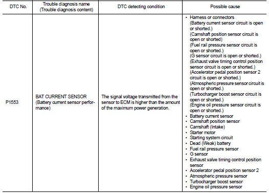
Nissan Juke Service and Repair Manual : P1553 battery current sensor
DTC Logic
DTC DETECTION LOGIC
DTC CONFIRMATION PROCEDURE
1.PRECONDITIONING
If DTC Confirmation Procedure has been previously conducted, always perform the following before conducting the next test.
1. Turn ignition switch OFF and wait at least 10 seconds.
2. Turn ignition switch ON.
3. Turn ignition switch OFF and wait at least 10 seconds.
TESTING CONDITION:
Before performing the following procedure, confirm that battery voltage is more
than 8 V at idle.
>> GO TO 2.
2.PERFORM DTC CONFIRMATION PROCEDURE
1. Start engine and wait at least 10 seconds.
2. Check 1st trip DTC.
Is 1st trip DTC detected? YES >> Proceed to EC-335, "Diagnosis Procedure".
NO >> INSPECTION END
Diagnosis Procedure
1.CHECK BATTERY CURRENT SENSOR POWER SUPPLY
1. Turn ignition switch OFF.
2. Disconnect battery current sensor harness connector.
3. Turn ignition switch ON.
4. Check the voltage between battery current sensor harness connector and ground.

Is the inspection result normal? YES >> GO TO 3.
NO >> GO TO 2.
2.CHECK SENSOR POWER SUPPLY CIRCUIT
1. Turn ignition switch OFF.
2. Disconnect ECM harness connector.
3. Check harness connector for short to power and short to ground, between the following terminals.
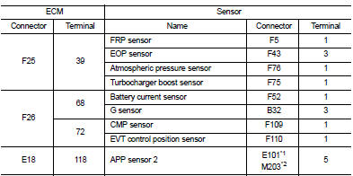
*1: LHD models or RHD with CVT models *2: RHD with M/T models
Is the inspection result normal? YES >> Perform the trouble diagnosis for power supply circuit.
NO >> Repair or replace error-detected parts.
3.CHECK BATTERY CURRENT SENSOR GROUND CIRCUIT
1. Turn ignition switch OFF.
2. Disconnect ECM harness connector.
3. Check the continuity between battery current sensor harness connector and ECM harness connector.
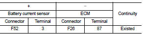
4. Also check harness for short to power.
Is the inspection result normal?
YES >> GO TO 4.
NO >> Repair or replace error-detected parts.
4.CHECK BATTERY CURRENT SENSOR INPUT SIGNAL CIRCUIT
1. Check the continuity between battery current sensor harness connector and ECM harness connector.
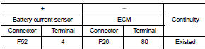
2. Also check harness for short to ground and to power.
Is the inspection result normal? YES >> GO TO 5.
NO >> Repair or replace error-detected parts
5.CHECK BATTERY CURRENT SENSOR
Check the battery current sensor. Refer to EC-330, "Component Inspection".
Is the inspection result normal? YES >> Check intermittent incident. Refer to GI-42, "Intermittent Incident".
NO >> Replace battery negative cable assembly. Refer to PG-125, "Exploded View".
Component Inspection
1.CHECK BATTERY CURRENT SENSOR
1. Turn ignition switch OFF.
2. Reconnect harness connectors disconnected.
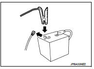
3. Disconnect battery negative cable.
4. Install jumper cable between battery negative terminal and body ground.
5. Turn ignition switch ON.
6. Check the voltage between ECM harness connector and ground.
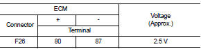
Before measuring the terminal voltage, confirm that the battery is fully charged. Refer to PG-111, "How to Handle Battery".
Is the inspection result normal? YES >> INSPECTION END
NO >> Replace battery negative cable assembly. Refer to PG-125, "Exploded View".
 P1551, P1552 battery current sensor
DTC Logic
DTC DETECTION LOGIC
DTC CONFIRMATION PROCEDURE
1.PRECONDITIONING
If DTC Confirmation Procedure has been previously conducted, always perform
the following before conducting
the next ...
 P1554 battery current sensor
DTC Logic
DTC DETECTION LOGIC
DTC CONFIRMATION PROCEDURE
1.PERFORM COMPONENT FUNCTION CHECK
Perform component function check. Refer to EC-337, "Component Function
Check".
NOTE:
U ...
Other materials:
Power supply and ground circuit
Navi control unit
NAVI CONTROL UNIT : Diagnosis Procedure
1.CHECK FUSE
Check for blown fuses.
Is inspection result OK?
YES >> GO TO 2.
NO >> Be sure to eliminate cause of malfunction before installing new fuse.
2.CHECK POWER SUPPLY CIRCUIT
Check voltage between NAVI control ...
Oil pan (lower)
Exploded View
1. O-ring
2. Oil pan (upper)
3. Oil level gauge guide
4. O-ring
5. Oil level gauge
6. Oil pump drive chain
7. Crankshaft sprocket
8. Oil pump sprocket
9. Oil pump chain tensioner
10. Oil pump
11. Drain plug
12. Drain plug washer
13. Oil pan (lower)
14. Oil fil ...
P0131 A/F sensor 1
DTC Logic
DTC DETECTION LOGIC
To judge the malfunction, the diagnosis checks that the A/F signal computed
by ECM from the A/F sensor 1
signal is not inordinately low.
DTC CONFIRMATION PROCEDURE
1.PRECONDITIONING
If DTC Confirmation Procedure has been previously conducted, always perform
...
