Nissan Juke Service and Repair Manual : P0730 incorrect gear ratio
DTC Logic
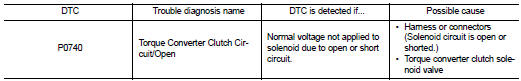
DTC DETECTION LOGIC
DTC CONFIRMATION PROCEDURE
NOTE
:
If “DTC CONFIRMATION PROCEDURE” has been previously performed, always turn
ignition switch
OFF and wait at least 10 seconds before performing the next test.
After the repair, perform the following procedure to confirm the malfunction is eliminated.
1.CHECK DTC DETECTION
 With CONSULT-III
1. Turn ignition switch ON.
2. Wait at least 10 consecutive seconds.
3. Select “Self Diagnostic Results” in “TRANSMISSION”.
 With GST
Follow the procedure “With CONSULT-III”.
Is “P0740” detected? YES >> Go to TM-215, "Diagnosis Procedure".
NO >> Check intermittent incident. Refer to GI-42, "Intermittent Incident".
Diagnosis Procedure
1. CHECK TORQUE CONVERTER CLUTCH SOLENOID VALVE CIRCUIT
1. Turn ignition switch OFF.
2. Disconnect TCM connector.
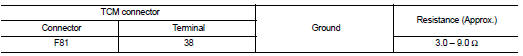
3. Check resistance between TCM connector terminal and ground.
Is the inspection result normal? YES >> GO TO 4.
NO >> GO TO 2.
2. CHECK HARNESS BETWEEN TCM AND TORQUE CONVERTER CLUTCH SOLENOID VALVE
1. Disconnect CVT unit harness connector.
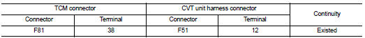
2. Check continuity between TCM connector terminal and CVT unit harness connector terminal.
3. If OK, check harness for short to ground and short to power.
4. If OK, check continuity between ground and transaxle assembly.
5. Reinstall any part removed.
Is the inspection result normal? YES >> GO TO 3.
NO >> Repair or replace damaged parts.
3.CHECK TORQUE CONVERTER CLUTCH SOLENOID VALVE
Check torque converter clutch solenoid valve. Refer to TM-216, "Component Inspection".
Is the inspection result normal? YES >> GO TO 4.
NO >> Repair or replace damaged parts.
4.CHECK TCM
Check TCM input/output signals. Refer to TM-164, "Reference Value".
Is the inspection result normal? YES >> Check intermittent incident. Refer to GI-42, "Intermittent Incident".
NO >> Replace the TCM. Refer to TM-280, "Removal and Installation".
Component Inspection
TORQUE CONVERTER CLUTCH SOLENOID VALVE
1.TORQUE CONVERTER CLUTCH SOLENOID VALVE
1. Turn ignition switch OFF.
2. Disconnect CVT unit harness connector.
3. Check resistance between CVT unit harness connector terminal and ground.

Is the inspection result normal? YES >> INSPECTION END
NO >> Replace the transaxle assembly. Refer to TM-301, "Removal and Installation".
 P0730 incorrect gear ratio
Description
TCM selects the gear ratio using the engine load (throttle position), the
primary pulley revolution speed, and
the secondary pulley revolution speed as input signal. Then it changes th ...
 P0744 torque converter
Description
This malfunction is detected when the torque converter clutch does not
lock-up as instructed by the TCM. This
is not only caused by electrical malfunction (circuits open or shorted), b ...
Other materials:
P0190 FRP sensor
DTC Logic
DTC DETECTION LOGIC
Diagnosis Procedure
1.CHECK GROUND CONNECTIONS
1. Turn ignition switch OFF.
2. Check ground connection E38. Refer to Ground inspection in GI-44, "Circuit
Inspection".
Is the inspection result normal?
YES >> GO TO 2.
NO >> Repair or ...
Bluetooth® Hands-Free Phone System
WARNING
• Use a phone after stopping your vehicle in a safe location. If you have
to use a phone while driving, exercise extreme caution at all times so full attention
may be given to vehicle operation.
• If you find yourself unable to devote full attention to vehicle operation while
tal ...
Evap canister
2WD : Hydraulic Layout
EVAPORATIVE EMISSION LINE DRAWING
1.EVAP canister purge volume control
solenoid valve
2. EVAP canister
3. EAVP line
4. Fuel line
NOTE:
Do not use soapy water or any type of solvent while installing vacuum hose or
purge hoses.
2WD : Removal and Installation
REMOV ...
