Nissan Juke Service and Repair Manual : P0112, P0113 IAT sensor
DTC Logic
DTC DETECTION LOGIC
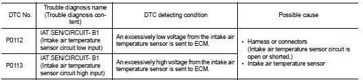
DTC CONFIRMATION PROCEDURE
1.PRECONDITIONING
If DTC Confirmation Procedure has been previously conducted, always perform the following procedure before conducting the next test.
1. Turn ignition switch OFF and wait at least 10 seconds.
2. Turn ignition switch ON.
3. Turn ignition switch OFF and wait at least 10 seconds.
>> GO TO 2.
2.PERFORM DTC CONFIRMATION PROCEDURE
1. Turn ignition switch ON and wait at least 5 seconds.
2. Check 1st trip DTC.
Is 1st trip DTC detected? YES >> Proceed to EC-198, "Diagnosis Procedure".
NO >> INSPECTION END
Diagnosis Procedure
1.CHECK INTAKE AIR TEMPERATURE SENSOR POWER SUPPLY
1. Turn ignition switch OFF.
2. Disconnect mass air flow sensor (with intake air temperature sensor) harness connector.
3. Turn ignition switch ON.
4. Check the voltage between mass air flow sensor harness connector and ground.
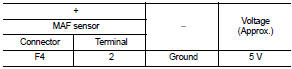
Is the inspection result normal? YES >> GO TO 3.
NO >> GO TO 2.
2.CHECK INTAKE AIR TEMPERATURE SENSOR POWER SUPPLY CIRCUIT
1. Turn ignition switch OFF.
2. Disconnect ECM harness connector.
3. Check the continuity between mass air flow sensor harness connector and ECM harness connector.
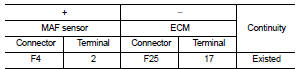
4. Also check harness for short to ground.
Is the inspection result normal? YES >> Perform the trouble diagnosis for power supply circuit.
NO >> Repair or replace error-detected parts.
3.CHECK INTAKE AIR TEMPERATURE SENSOR GROUND CIRCUIT
1. Turn ignition switch OFF.
2. Disconnect ECM harness connector.
3. Check the continuity between mass air flow sensor harness connector and ECM harness connector.
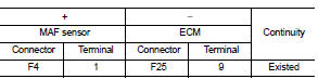
4. Also check harness for short to power.
Is the inspection result normal? YES >> GO TO 4.
NO >> Repair or replace error-detected parts.
4.CHECK INTAKE AIR TEMPERATURE SENSOR
Check the intake air temperature sensor. Refer to EC-199, "Component Inspection".
Is the inspection result normal? YES >> Check intermittent incident. Refer to GI-42, "Intermittent Incident".
NO >> Replace mass air flow sensor (with intake air temperature sensor). Refer to EM-26, "Exploded View".
Component Inspection
1.CHECK INTAKE AIR TEMPERATURE SENSOR
1. Turn ignition switch OFF.
2. Disconnect mass air flow sensor harness connector.
3. Check resistance between mass air flow sensor terminals as per the following.
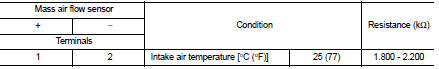
Is the inspection result normal? YES >> INSPECTION END
NO >> Replace mass air flow sensor (with intake air temperature sensor). Refer to EM-26, "Exploded View".
 P0107, P0108 atmospheric pressure
sensor
P0107, P0108 atmospheric pressure
sensor
DTC Logic
DTC DETECTION LOGIC
DTC CONFIRMATION PROCEDURE
1.PRECONDITIONING
If DTC Confirmation Procedure has been previously conducted, always perform
the following procedure
before conducti ...
 P0117, P0118 ECT sensor
DTC Logic
DTC DETECTION LOGIC
DTC CONFIRMATION PROCEDURE
1.PRECONDITIONING
If DTC Confirmation Procedure has been previously conducted, always perform
the following procedure
before conductin ...
Other materials:
Audible reminders
Key reminder chime
Models with Intelligent Key system:
A chime will sound if the driver side door is opened while the ignition switch
is pushed to the ACC position.
Make sure the ignition switch is pushed to the OFF position, and take the Intelligent
Key with you when leaving the vehicle.
Mo ...
Back door does not opened
Diagnosis Procedure
1.CHECK BACK DOOR OPENER SWITCH
Check back door opener switch.
Refer to DLK-69, "Component Function Check".
Is the inspection result normal?
YES >> GO TO 2.
NO >> Repair or replace the malfunctioning parts.
2.CHECK BACK DOOR OPENER ACTUATOR
C ...
Power generation voltage variable control system operation
inspection
Inspection Procedure
CAUTION:
When performing this inspection, always use a charged battery that has completed
the battery inspection.
(When the charging rate of the battery is low, the response speed of the voltage
change will
become slow. This can cause an incorrect inspection.)
1.CHECK ...
