Nissan Juke Service and Repair Manual : P0087, P0088, P0090 FRP control system
DTC Logic
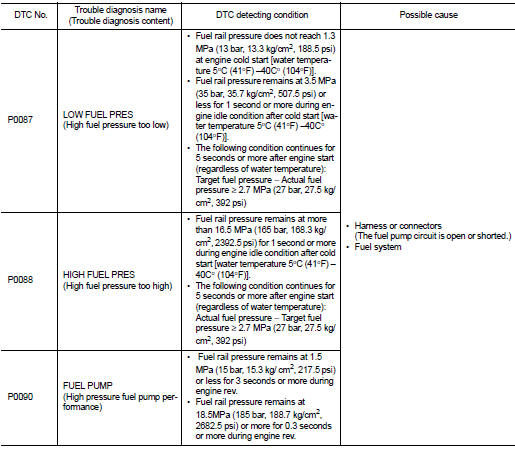
DTC DETECTION LOGIC
NOTE
:
• If DTC P0087 or P0090 is displayed with DTC P1197, first perform the trouble
diagnosis for DTC
P1197.
• DTC P0087 or P0090 may be displayed when running out of gas.
DTC CONFIRMATION PROCEDURE
1.PRECONDITIONING
If DTC Confirmation Procedure has been previously conducted, always perform the following procedure before conducting the next test.
1. Turn ignition switch OFF and wait at least 10 seconds.
2. Turn ignition switch ON.
3. Turn ignition switch OFF and wait at least 10 seconds.
TESTING CONDITION:
Before performing the following procedure, confirm that battery voltage is 11 V
or more at idle.
2.PERFORM DTC CONFIRMATION PROCEDURE-I
1. Check that the fuel tank is 1/8 full of fuel.
2. Warm up the engine to the normal operating temperature and keep the engine speed at idle for 10 seconds.
NOTE
:
Warm up the engine until “COOLAN TEMP/S” on “DATA MONITOR” mode of “ENGINE”
using CONSULTIII
reaches at least 70°C (158°F).
3. Check 1st trip DTC.
Is 1st trip DTC detected? YES >> Proceed to EC-183, "Diagnosis Procedure".
NO >> GO TO 3.
3.PERFORM DTC CONFIRMATION PROCEDURE-II
1. Cool the engine until the engine coolant temperature reaches 60°C (140°F) or less.
2. Start the engine and wait at least 40 seconds.
3. Check 1st trip DTC.
Is 1st trip DTC detected? YES >> Proceed to EC-183, "Diagnosis Procedure".
NO >> INSPECTION END
Diagnosis Procedure
1.PERFORM THE HIGH PRESSURE FUEL PUMP COMPONENT INSPECTION
Perform the high pressure fuel pump component inspection. Refer to EC-183, "Component Inspection".
Is the inspection result normal? YES >> GO TO 2.
NO >> Replace the fuel pump. FL-6, "2WD : Exploded View" (2WD) or FL-10, "4WD : Exploded View" (4WD).
2.CHECK FUEL LEAKAGE
1. Start the engine.
2. Visually check that the fuel pump, fuel rail, and fuel piping have no fuel leakage.
Is the inspection result normal? YES >> Check that the fuel system has no breakage, bend, and crush. Refer to FL-5, "Inspection".
NO >> Repair or Replace the error-detected parts.
Component Inspection
1.CHECK HIGH PRESSURE FUEL PUMP-I
1. Turn ignition switch OFF.
2. Disconnect high pressure fuel pump harness connector.
3. Check the resistance between high pressure fuel pump terminals as follows.

Is the inspection result normal? YES >> GO TO 2.
NO >> Replace high pressure fuel pump. Refer to EM-43, "Exploded View".
2.CHECK HIGH PRESSURE FUEL PUMP-II
 With CONSULT-III
1. Reconnect high pressure fuel pump harness connector.
2. Start the engine.
3. Check “FUEL PRES SEN” in “DATA MONITOR” of “ENGINE” using CONSULT-III.

 Without CONSULT-III
1. Start the engine.
2. Check fuel rail pressure sensor signal voltage.
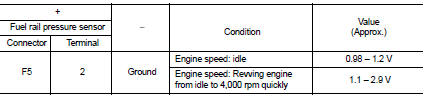
Is the inspection result normal? YES >> INSPECTION END
NO >> Replace high pressure fuel pump. Refer to EM-43, "Exploded View".
 P0078 EVT control solenoid valve
DTC Logic
DTC DETECTION LOGIC
DTC CONFIRMATION PROCEDURE
1.PRECONDITIONING
If DTC Confirmation Procedure has been previously conducted, always perform
the following procedure
before conductin ...
 P0097, P0098 IAT sensor 2
DTC Logic
DTC DETECTION LOGIC
DTC CONFIRMATION PROCEDURE
1.PRECONDITIONING
If DTC Confirmation Procedure has been previously conducted, always perform
the following procedure
before conductin ...
Other materials:
High pressure supply pump
Exploded View
1. High pressure supply pump protector
2. High pressure supply pump
: N·m (kg-m, ft-lb)
Removal and Installation
REMOVAL
CAUTION:
• Be sure to read “Precautions for Diesel Equipment”. Refer to EM-263,
"Precaution for Diesel Equipment".
• Wait until the f ...
On Board Diagnostic (OBD) System of Engine and CVT
The ECM has an on board diagnostic system. It will light up the malfunction
indicator (MI) to warn the driver of
a malfunction causing emission deterioration.
CAUTION:
• Be sure to turn the ignition switch OFF and disconnect the negative battery
cable before any repair
or inspection work ...
Removal and Disassembly
• When instructed to use SST, use specified tools. Always be careful to work
safely, avoid forceful or uninstructed
operations.
• Exercise maximum care to avoid damage to mating or sliding surfaces.
• Dowel pins are used for several parts alignment. When replacing and
reassembling parts ...
