Nissan Juke Service and Repair Manual : P0097, P0098 IAT sensor 2
DTC Logic
DTC DETECTION LOGIC
DTC CONFIRMATION PROCEDURE
1.PRECONDITIONING
If DTC Confirmation Procedure has been previously conducted, always perform the following procedure before conducting the next test.
1. Turn ignition switch OFF and wait at least 10 seconds.
2. Turn ignition switch ON.
3. Turn ignition switch OFF and wait at least 10 seconds.
TEST CONDITION:
Before performing the following procedure, confirm that battery voltage is more
than 11 V at idle.
>> GO TO 2.
2.PERFORM DTC CONFIRMATION PROCEDURE
1. Start engine and let it idle for at least 5 seconds.
2. Check 1st trip DTC.
Is 1st trip DTC detected? YES >> Proceed to EC-186, "Diagnosis Procedure".
NO >> INSPECTION END
Diagnosis Procedure
1.CHECK INTAKE AIR TEMPERATURE SENSOR 2 POWER SUPPLY CIRCUIT-I
1. Turn ignition switch OFF.
2. Disconnect turbocharger boost sensor harness connector.
3. Turn ignition switch ON.
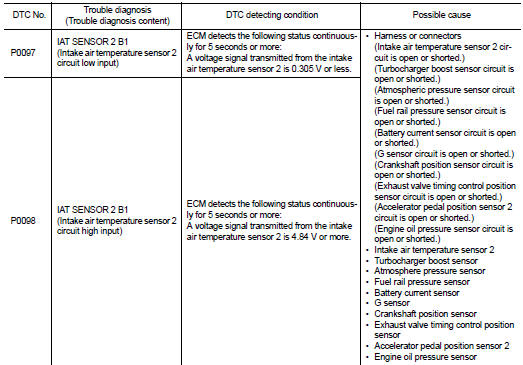
4. Check the voltage between turbocharger boost sensor harness connector terminals.
Is the inspection result normal? YES >> GO TO 2.
NO >> GO TO 4.
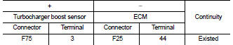
2.CHECK INTAKE AIR TEMPERATURE SENSOR 2 SIGNAL CIRCUIT
1. Turn ignition switch OFF.
2. Disconnect ECM harness connector.
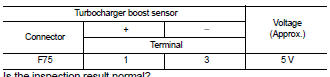
3. Check the continuity between turbocharger boost sensor harness connector and ECM harness connector.
4. Also check harness for short to ground and short to power.
Is the inspection result normal? YES >> GO TO 3.
NO >> Repair or replace error-detected parts.
3.CHECK INTAKE AIR TEMPERATURE SENSOR 2
Check intake air temperature sensor 2. Refer to EC-187, "Component Inspection".
Is the inspection result normal? YES >> Check intermittent incident. Refer to GI-42, "Intermittent Incident".
NO >> Replace turbocharger boost sensor (with intake air temperature sensor 2). Refer to EM-28, "Exploded View".
4.CHECK INTAKE AIR TEMPERATURE SENSOR 2 POWER SUPPLY CIRCUIT-II
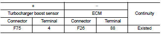
Check the voltage between turbocharger boost sensor harness connector terminal and ground.
Is the inspection result normal? YES >> GO TO 5.
NO >> GO TO 7.
5.CHECK INTAKE AIR TEMPERATURE SENSOR 2 GROUND CIRCUIT
1. Turn ignition switch OFF.
2. Disconnect ECM harness connector.
3. Check the continuity between turbocharger boost sensor harness connector and ECM harness connector.
Is the inspection result normal? YES >> GO TO 6.
NO >> Repair or replace error-detected parts.
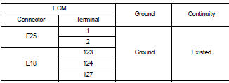
6.CHECK ECM GROUND CIRCUIT
Check the continuity between ECM harness connector and ground.
Is the inspection result normal? YES >> Check intermittent incident. Refer to GI-42, "Intermittent Incident".
NO >> Repair or replace error-detected parts.
7.CHECK SENSOR POWER SUPPLY CIRCUIT
1. Turn ignition switch OFF.
2. Disconnect ECM harness connectors and each sensor harness connectors 3. Check harness connector for short to power and short to ground, between the following terminals.
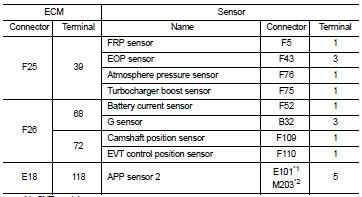
*1: CVT models
*2: RHD with M/T models
Is the inspection result normal? YES >> Perform the trouble diagnosis for power supply circuit.
NO >> Repair or replace error-detected parts.
Component Inspection
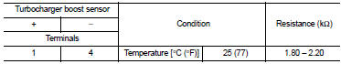
1.CHECK INTAKE AIR TEMPERATURE SENSOR 2
1. Turn ignition switch OFF.
2. Disconnect turbocharger boost sensor harness connector.
3. Check resistance between turbocharger boost sensor terminals as follows.
Is the inspection result normal? YES >> INSPECTION END NO >> Replace turbocharger boost sensor (with intake air temperature sensor 2). Refer to EM-28, "Exploded View".
 P0087, P0088, P0090 FRP control system
DTC Logic
DTC DETECTION LOGIC
NOTE:
• If DTC P0087 or P0090 is displayed with DTC P1197, first perform the trouble
diagnosis for DTC
P1197.
• DTC P0087 or P0090 may be displayed when runnin ...
 P0102, P0103 MAF sensor
DTC Logic
DTC DETECTION LOGIC
DTC CONFIRMATION PROCEDURE
1.PRECONDITIONING
If DTC Confirmation Procedure has been previously conducted, always perform
the following procedure
before conductin ...
Other materials:
ECU diagnosis information
IPDM E/R
Reference Value
VALUES ON THE DIAGNOSIS TOOL
TERMINAL LAYOUT
PHYSICAL VALUES
*1: MR16DDT engine models
*2: Except MR16DDT engine models
*3: CVT models
*4: M/T models
*5: With daytime running light system
*6: Without daytime running light system
*7: K9K engine models ...
Component parts
Component Parts Location
1. Front door speaker LH
2. Rear door speaker LH
3. Rear view camera
4. Rear door speaker RH
5. Antenna rod
6. Antenna base (antenna amp.)
7. Front door speaker RH
8. Microphone
9. GPS antenna
10. Tweeter LH
11. Steering switch
12. USB connector and AUX ...
Forward-facing child restraint installation using the seat belts
WARNING
The three-point seat belt with Automatic Locking Retractor (ALR) must be used
when installing a child restraint.
Failure to use the ALR mode will result in the child restraint not being properly
secured. The restraint could tip over or be loose and cause injury to a child in
a sudden ...
