Nissan Juke Service and Repair Manual : P0102, P0103 MAF sensor
DTC Logic
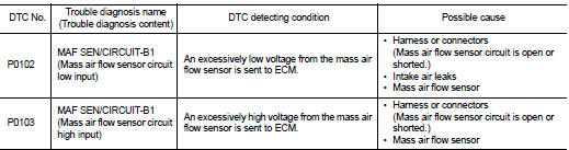
DTC DETECTION LOGIC
DTC CONFIRMATION PROCEDURE
1.PRECONDITIONING
If DTC Confirmation Procedure has been previously conducted, always perform the following procedure before conducting the next test.
1. Turn ignition switch OFF and wait at least 10 seconds.
2. Turn ignition switch ON.
3. Turn ignition switch OFF and wait at least 10 seconds.
Which DTC is detected? P0102 >> GO TO 2.
P0103 >> GO TO 3.
2.PERFORM DTC CONFIRMATION PROCEDURE FOR DTC P0102
1. Start engine and wait at least 5 seconds.
2. Check DTC.
Is DTC detected? YES >> Proceed to EC-189, "Diagnosis Procedure".
NO >> INSPECTION END 3.PERFORM DTC CONFIRMATION PROCEDURE FOR DTC P0103-I
1. Turn ignition switch ON and wait at least 5 seconds.
2. Check DTC.
Is DTC detected? YES >> Proceed to EC-189, "Diagnosis Procedure".
NO >> GO TO 4.
4.PERFORM DTC CONFIRMATION PROCEDURE FOR DTC P0103-II
1. Start engine and wait at least 5 seconds.
2. Check DTC.
Is DTC detected? YES >> Proceed to EC-189, "Diagnosis Procedure".
NO >> INSPECTION END
Diagnosis Procedure
1.INSPECTION START
Confirm the detected DTC.
Which DTC is detected? P0102 >> GO TO 2.
P0103 >> GO TO 3.
2.CHECK INTAKE SYSTEM
Check the following for connection.
• Air duct
• Vacuum hoses
• Intake air passage between air duct to intake manifold
Is the inspection result normal? YES >> GO TO 3.
NO >> Reconnect the parts. Refer to EM-26, "Exploded View".
3.CHECK MAF SENSOR POWER SUPPLY
1. Turn ignition switch OFF.
2. Disconnect mass air flow (MAF) sensor harness connector.
3. Turn ignition switch ON.
4. Check the voltage between MAF sensor harness connector and ground.
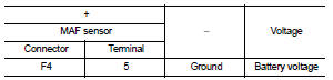
Is the inspection result normal? YES >> GO TO 5.
NO >> GO TO 4.
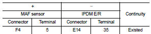
4.CHECK MAF SENSOR POWER SUPPLY CIRCUIT
1. Turn ignition switch OFF.
2. Disconnect IPDM E/R harness connector.
3. Check the continuity between MAF sensor harness connector and IPDM E/R harness connector.
4. Also check harness for short to ground.
Is the inspection result normal? YES >> Perform the trouble diagnosis for power supply circuit.
NO >> Repair or replace error-detected parts.
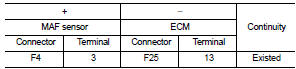
5.CHECK MAF SENSOR GROUND CIRCUIT
1. Turn ignition switch OFF.
2. Disconnect ECM harness connector.
3. Check the continuity between MAF sensor harness connector and ECM harness connector.
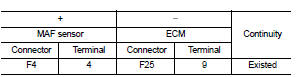
Is the inspection result normal? YES >> GO TO 6.
NO >> Repair or replace error-detected parts.
6.CHECK MAF SENSOR INPUT SIGNAL CIRCUIT
1. Check the continuity between MAF sensor harness connector and ECM harness connector.
2. Also check harness for short to ground and to power.
Is the inspection result normal? YES >> GO TO 7.
NO >> Repair open circuit or short to ground or short to power in harness or connectors.
7.CHECK MASS AIR FLOW SENSOR
Check the mass air flow sensor. Refer to EC-191, "Component Inspection".
Is the inspection result normal? YES >> Check intermittent incident. Refer to GI-42, "Intermittent Incident".
NO >> Replace mass air flow sensor. Refer to EM-26, "Exploded View".
Component Inspection
1.CHECK MASS AIR FLOW SENSOR-I
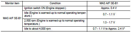
 With CONSULT-III
1. Turn ignition switch OFF.
2. Reconnect all harness connectors disconnected.
3. Start engine and warm it up to normal operating temperature.
4. Connect CONSULT-III and select “DATA MONITOR” mode of “ENGINE”.
5. Select “MAS A/F SE-B1” and check indication.
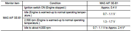
*: Check for linear voltage rise in response to engine being increased to about 4,000 rpm.
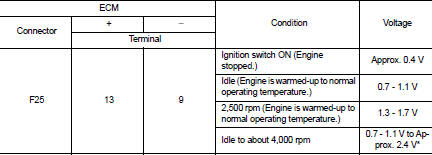
 Without CONSULT-III
1. Turn ignition switch OFF.
2. Reconnect all harness connectors disconnected.
3. Start engine and warm it up to normal operating temperature.
4. Check the voltage between ECM harness connector and ground.
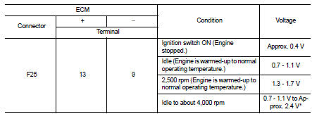
*: Check for linear voltage rise in response to engine being increased to about 4,000 rpm.
Is the inspection result normal?
YES >> INSPECTION END
NO >> GO TO 2.
2.CHECK FOR THE CAUSE OF UNEVEN AIR FLOW THROUGH MASS AIR FLOW SENSOR
1. Turn ignition switch OFF.
2. Check for the cause of uneven air flow through mass air flow sensor. Refer to the following.
- Crushed air ducts
- Malfunctioning seal of air cleaner element
- Uneven dirt of air cleaner element
- Improper specification of intake air system parts
Is the inspection result normal? YES >> GO TO 4.
NO >> GO TO 3.
3.CHECK MASS AIR FLOW SENSOR-II
 With CONSULT-III
1. Repair or replace malfunctioning part.
2. Start engine and warm it up to normal operating temperature.
3. Connect CONSULT-III and select “DATA MONITOR” mode of “ENGINE”.
4. Select “MAS A/F SE-B1” and check indication.
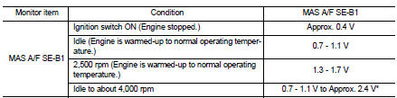
*: Check for linear voltage rise in response to engine being increased to about 4,000 rpm.
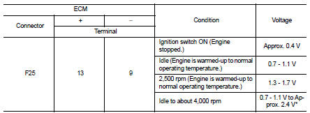
 Without CONSULT-III
1. Repair or replace malfunctioning part.
2. Start engine and warm it up to normal operating temperature.
3. Check the voltage between ECM harness connector and ground.
*: Check for linear voltage rise in response to engine being increased to about 4,000 rpm.
Is the inspection result normal? YES >> INSPECTION END
NO >> GO TO 4.
4.CHECK MASS AIR FLOW SENSOR-III
 With CONSULT-III
1. Turn ignition switch OFF.
2. Disconnect mass air flow sensor harness connector and reconnect it again.
3. Start engine and warm it up to normal operating temperature.
4. Connect CONSULT-III and select “DATA MONITOR” mode of “ENGINE”.
5. Select “MAS A/F SE-B1” and check indication.
*: Check for linear voltage rise in response to engine being increased to about 4,000 rpm.
Without CONSULT-III
1. Turn ignition switch OFF.
2. Disconnect mass air flow sensor harness connector and reconnect it again.
3. Start engine and warm it up to normal operating temperature.
4. Check the voltage between ECM harness connector and ground.
*: Check for linear voltage rise in response to engine being increased to about 4,000 rpm.
Is the inspection result normal? YES >> INSPECTION END
NO >> Clean or replace mass air flow sensor. Refer to EM-26, "Exploded View".
 P0097, P0098 IAT sensor 2
DTC Logic
DTC DETECTION LOGIC
DTC CONFIRMATION PROCEDURE
1.PRECONDITIONING
If DTC Confirmation Procedure has been previously conducted, always perform
the following procedure
before conductin ...
 P0107, P0108 atmospheric pressure
sensor
P0107, P0108 atmospheric pressure
sensor
DTC Logic
DTC DETECTION LOGIC
DTC CONFIRMATION PROCEDURE
1.PRECONDITIONING
If DTC Confirmation Procedure has been previously conducted, always perform
the following procedure
before conducti ...
Other materials:
Steering wheel
Tilt and telescopic operation
To alter the driving posture, push the mechanical adjustment lock lever 1 straight down to release the column grip:
Manually tilt the steering wheel housing up or down along path 2 to match your eye line and shoulder height.
...
Precaution for Supplemental Restraint System (SRS) "AIR BAG" and "SEAT BELT
PRE-TENSIONER"
The Supplemental Restraint System such as “AIR BAG” and “SEAT BELT PRE-TENSIONER”,
used along
with a front seat belt, helps to reduce the risk or severity of injury to the
driver and front passenger for certain
types of collision. Information necessary to service the system safely is
...
Front wheel hub and K
Exploded View
1. Steering knuckle
2. Splash guard
3. Hub bolt
4. Wheel hub assembly (Bearing-integrated
type)
5. Disc rotor
6. Wheel hub lock nut
7. Adjusting cap
8. Cotter pin
A. Tightening must be done following the installation procedure. Refer to
FAX-68, "Removal and Insta ...
