Nissan Juke Service and Repair Manual : Oil pan (upper)
Exploded View
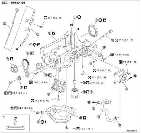
1. O-ring
2. Oil pan (upper)
3. Oil level gauge guide
4. O-ring
5. Oil level gauge
6. Oil pump drive chain
7. Crankshaft sprocket
8. Oil pump sprocket
9. Oil pump chain tensioner
10. Oil pump
11. Drain plug
12. Drain plug washer
13. Oil pan (lower)
14. Oil filter
15. Connector bolt
16. Clamp
17. Water hose
18. Oil cooler
19. Crankshaft position sensor
20. Oil level sensor
21. Rear oil seal
A. Refer to LU-11
B. Oil pan side
C.To thermostat haosing (M/T models)
To CVT fluid cooler (CVT models)
D. Oil pan side
 : N┬Ęm (kg-m, ft-lb)
 : N┬Ęm (kg-m, in-lb)
 : Always replace after every
disassembly.
 : Should be lubricated with oil.
 : Sealing point
Removal and Installation
REMOVAL
1. Remove oil pan (lower). Refer to EM-99, "Exploded View".
2. Remove oil filter. Refer to LU-11, "Removal and Installation".
3. Remove front cover, timing chain, oil pump drive chain, and other related parts. Refer to EM-67, "Exploded View".
4. Remove oil level gauge and oil level gauge guide.
5. Remove oil pump. Refer to LU-15, "Exploded View".
NOTE
:
The oil pan (upper) can be removed and installed without removing the oil pump.
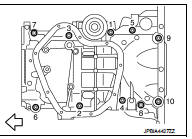
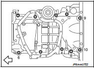
6. Remove oil pan (upper) with the following procedure: a. Loosen bolts in reverse order as shown in the figure.
 : Engine front
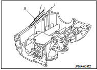
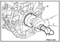
b. Insert a screwdriver shown by the arrow ( ) in the figure and open up a crack between oil pan (upper) and cylinder block.
: Engine front
CAUTION:
A more adhesive liquid gasket is applied compared to previous
types when shipped, so it should not be forced off the
position not specified.
![c. Insert seal cutter [SST: KV10111100 (J-37228)] between oil pan (upper) and](images/books/335/3/index.86.jpg)
c. Insert seal cutter [SST: KV10111100 (J-37228)] between oil pan (upper) and cylinder block, and slide it by tapping on the side of the tool with a hammer.
CAUTION:
Be careful not to damage the mating surface.
7. Remove O-ring between cylinder block and oil pan (upper).
INSTALLATION
1. Install oil pan (upper) with the following procedure:
A. Use a scraper (a) to remove old liquid gasket from mating surfaces.
ŌĆó Remove the old liquid gasket from mating surface of cylinder block.
ŌĆó Remove old liquid gasket from the bolt holes and threads.
Caution:
never scratch or damage the mating surfaces when cleaning
off old liquid gasket.
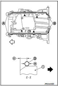
B. Apply a continuous bead of liquid gasket (d) with a tube presser (commercial service tool) as shown in the figure.
1 : Oil pan (upper)
a : 2 mm (0.08 In) protruded to outside
b : 2 mm (0.08 In) protruded to rear oil seal mounting side
c : 5.5 - 7.5 Mm (0.217 - 0.295 In)
e : 4.0 - 5.0 Mm (0.157 - 0.197 In)
 : engine front
 : engine outside
Use genuine liquid gasket or equivalent.
Caution:
ŌĆó apply liquid gasket to outside of bolt hole for the positions
shown by  marks.
ŌĆó Attaching should be done within 5 minutes after liquid
gasket application.
c. Install new O-ring at cylinder block side.
CAUTION:C. Install new o-ring at cylinder block side.
Caution:
install avoiding misalignment of o-ring.
D. Tighten bolts in numerical order as shown in the figure.
Install avoiding misalignment of O-ring.
d. Tighten bolts in numerical order as shown in the figure.
: Engine front
2. Install rear oil seal with the following procedure.
Caution:
ŌĆó the installation of rear oil seal should be completed within 5 minutes after
installing oil pan
(upper).
ŌĆó Always replace rear oil seal with new one.
ŌĆó Never touch oil seal lip.
A. Wipe off liquid gasket protruding to the rear oil seal mounting part of oil pan (upper) and cylinder block using a scraper.
B. Apply engine oil to entire outside area of rear oil seal.
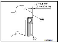
C. Press-fit the rear oil seal using a suitable drift (a) with outer diameter 115 mm (4.53 In) and inner diameter 90 mm (3.54 In).
ŌĆó Press-fit to the specified dimensions as shown in the figure.
1 : Rear oil seal
A : Cylinder block rear end surface
CAUTION:
ŌĆó Never touch the grease applied to the oil seal lip.
ŌĆó Be careful not to damage the rear oil seal mounting part of oil pan (upper) and cylinder block or the crankshaft.
ŌĆó Press-fit straight, checking that rear oil seal does not curl or tilt.
NOTE:
The standard surface of the dimension is the rear end surface of cylinder block.
3. Install in the reverse order of removal, for the rest of parts.
Inspection
INSPECTION AFTER REMOVAL
Clean oil strainer portion (part of the oil pump) if any object attached.
 Cylinder head
Exploded View
REMOVAL
1. Cylinder head assembly
2. Cylinder head bolt
3. Cylinder head gasket
A. Tightening must be done following
the installation procedure.
Refer to EM-91
: N┬Ęm (kg-m ...
 Cylinder block
Exploded View
1. Cylinder block
2. Top ring
3. Second ring
4. Oil ring
5. Piston
6. Piston pin
7. Snap ring
8. Connecting rod
9. Connecting rod bearing (upper)
10. Connecting rod be ...
Other materials:
Rear suspension assembly
Exploded View
1. Rear suspension member
2. Rebound stopper
3. Washer
: Vehicle front
N┬Ęm (kg-m, ft-lb)
Removal and Installation
REMOVAL
1. Remove tires. Refer to WT-7, "Removal and Installation".
2. Remove center pipe. Refer to EX-6, "Removal and Installation".
3. ...
Precaution Necessary for Steering Wheel Rotation after Battery Disconnect
NOTE:
ŌĆó Before removing and installing any control units, first turn the ignition
switch to the LOCK position, then disconnect
both battery cables.
ŌĆó After finishing work, confirm that all control unit connectors are connected
properly, then re-connect both
battery cables.
ŌĆó Always us ...
Precaution for Disposal
ŌĆó Before disposing of air bag module, pop-up roll bar and seat belt pre-tensioner,
or vehicles equipped with
such systems, deploy the systems. If such systems have already been deployed due
to an accident, dispose
of them as indicated in Disposing of Air Bag Module, Pop-up Roll Bar and Seat ...
