Nissan Juke Service and Repair Manual : Keyfob battery
Exploded View
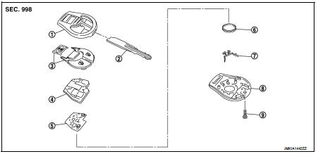
1. Upper case
2. Key
3. Switch cover
4. Switch rubber
5. Board surface
6. Battery
7. plate
8. Lower case
9. Screw
Removal and Installation
REMOVAL
1. Remove screw (9) on the rear of keyfob.
2. Place the key with the lower case (8) facing up. Set a screw-driver wrapped with tape between upper case (1) and lower case (8) and then separate the lower case (8) from the upper case (1).
CAUTION:
• Do not touch the circuit board or battery terminal.
• The keyfob is water-resistant. However, if it does get wet, immediately wipe it dry.
3. When replacing the circuit board assembly, remove circuit board assembly from the upper case (1).
[Circuit board assembly: Switch rubber (4) + Board surface (5)]
CAUTION:
Do not touch the printed circuits directly.
4. Remove the battery (6) from the lower case (8) and replace it.
Battery replacement : Coin-type lithium battery (CR1620)
CAUTION:
When replacing battery, keep dirt, grease, and other foreign materials off the
electrode contact
area.
5. After replacement, fit the lower and upper cases together, part (4), (7) and tighten with the screw.
CAUTION:
After replacing the battery, Be sure to check that door locking operates
normally using the keyfob.
Refer to DLK-403, "Component Function Check".
INSTALLATION
Install in the reverse order of removal.
 Remote keyless entry receiver
Removal and Installation
REMOVAL
1. Remove the glove box assembly. Refer to IP-13, "Removal and
Installation".
2. Remove the remote keyless entry receiver (1) mounting bolt (A),
and th ...

Other materials:
Component parts
Component Parts Location
1. BCM
Refer to BCS-6, "BODY CONTROL
SYSTEM : Component Parts Location"
(with Intelligent Key) or BCS-96,
"BODY CONTROL SYSTEM : Component
Parts Location" (without Intelligent
Key)
2. Power window main switch
3. Front power window motor (drive ...
A/C on signal
Component Function Check
1.CHECK A/C ON SIGNAL
With CONSULT-III
1. Turn ignition switch ON.
2. Operate blower motor.
3. Select “AIR CONDITIONER” of “BCM” using CONSULT-III.
4. Select “AIR COND SW” in “DATA MONITOR” mode.
5. Check A/C ON signal when the A/C switch is operated.
...
Speed limiter main switch
Component Function Check
1.CHECK SPEED LIMITER MAIN SWITCH FUNCTION
With CONSULT-III
1. Turn ignition switch ON.
2. Select “ENGINE” using CONSULT-III.
3. Select “SL MAIN SW” in “DATA MONITOR” mode.
4. Check “SL MAIN SW” indication under the following condition.
Without CONSU ...
