Nissan Juke Service and Repair Manual : Idle air volume learning
Description
Idle Air Volume Learning is a function of ECM to learn the idle air volume that keeps each engine idle speed within the specific range. It must be performed under any of the following conditions: ÔÇó Each time electric throttle control actuator or ECM is replaced.
ÔÇó Idle speed or ignition timing is out of specification.
Work Procedure
1.PRECONDITIONING
Make sure that all of the following conditions are satisfied.
Learning will be cancelled if any of the following conditions are missed for even a moment.
ÔÇó Battery voltage: More than 12.9 V (At idle) ÔÇó Engine coolant temperature: 70 - 100┬░C (158 - 212┬░F) ÔÇó Selector lever : P or N (CVT), Neutral (M/T) ÔÇó Electric load switch: OFF
(Air conditioner, headlamp, rear window defogger) On vehicles equipped with daytime running light systems, set lighting switch to the 1st position to light only small lamps.
ÔÇó Steering wheel: Neutral (Straight-ahead position) ÔÇó Vehicle speed: Stopped ÔÇó Transmission: Warmed-up - CVT models
ÔÇó With CONSULT-III: Drive vehicle until ÔÇťATF TENP SENÔÇŁ in ÔÇťDATA MONITORÔÇŁ mode of ÔÇťCVTÔÇŁ system indicates less than 0.9 V.
ÔÇó Without CONSULT-III: Drive vehicle for 10 minutes.
- M/T models
ÔÇó Drive vehicle for 10 minutes.
Do you have CONSULT-III?
YES >> GO TO 2.
NO >> GO TO 3.
2.IDLE AIR VOLUME LEARNING
 With CONSULT-III
1. Perform Accelerator Pedal Released Position Learning. Refer to EC-134, "Work Procedure".
2. Perform Throttle Valve Closed Position Learning. Refer to EC-135, "Work Procedure".
3. Start engine and warm it up to normal operating temperature.
4. Select ÔÇťIDLE AIR VOL LEARNÔÇŁ in ÔÇťWORK SUPPORTÔÇŁ mode of ÔÇťENGINEÔÇŁ.
5. Touch ÔÇťSTARTÔÇŁ and wait 20 seconds.
Is ÔÇťCMPLTÔÇŁ displayed on CONSULT-III screen? YES >> GO TO 4.
3.IDLE AIR VOLUME LEARNING
 Without CONSULT-III
NOTE
:
ÔÇó It is better to count the time accurately with a clock.
ÔÇó It is impossible to switch the diagnostic mode when an accelerator pedal position sensor circuit has a malfunction.
1. Perform Accelerator Pedal Released Position Learning. Refer to EC-134, "Work Procedure".
2. Perform Throttle Valve Closed Position Learning. Refer to EC-135, "Work Procedure".
3. Start engine and warm it up to normal operating temperature.
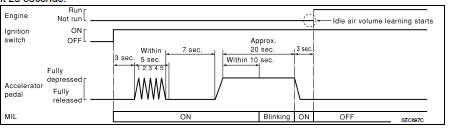
4. Turn ignition switch OFF and wait at least 10 seconds.
5. Confirm that accelerator pedal is fully released, turn ignition switch ON and wait 3 seconds.
6. Repeat the following procedure quickly five times within 5 seconds.
- Fully depress the accelerator pedal.
- Fully release the accelerator pedal.
7. Wait 7 seconds, fully depress the accelerator pedal and keep it for approx. 20 seconds until the MIL stops blinking and turned ON.
8. Fully release the accelerator pedal within 3 seconds after the MIL turned ON.
9. Start engine and let it idle.
10. Wait 20 seconds.
>> GO TO 4
4.CHECK IDLE SPEED AND IGNITION TIMING
Rev up the engine two or three times and make sure that idle speed and ignition timing are within the specifications.
For specification, refer to EC-449, "Idle Speed" and EC-449, "Ignition Timing".
Is the inspection result normal? YES >> INSPECTION END NO >> GO TO 5.
5.DETECT MALFUNCTIONING PART
Check the following
ÔÇó Check that throttle valve is fully closed.
ÔÇó Check PCV valve operation.
ÔÇó Check that downstream of throttle valve is free from air leakage.
Is the inspection result normal? YES >> GO TO 6.
NO >> Repair or replace malfunctioning part.
6.DETECT MALFUNCTIONING PART
Engine component parts and their installation condition are questionable. Check and eliminate the cause of the incident.
It is useful to perform ÔÇťTROUBLE DIAGNOSIS - SPECIFICATION VALUEÔÇŁ. Refer toEC-147, "Description".
If any of the following conditions occur after the engine has started, eliminate the cause of the incident and perform Idle Air Volume Learning all over again: ÔÇó Engine stalls.
ÔÇó Erroneous idle.
>> INSPECTION END
 Throttle valve closed position
learning
Throttle valve closed position
learning
Description
Throttle Valve Closed Position Learning is a function of ECM to learn the
fully closed position of the throttle
valve by monitoring the throttle position sensor output signal. It must ...
 G sensor calibration
Description
ECM stores calibration data (inherent characteristic value) of G sensor to
provide accurate control. Therefore,
it is required to perform calibration of G sensor after the following wo ...
Other materials:
U0141 lost communication (BCM A)
Description
CAN (Controller Area Network) is a serial communication line for real-time
application. It is an on-vehicle multiplex
communication line with high data communication speed and excellent malfunction
detection ability.
Many electronic control units are equipped onto a vehicle, and ...
Front door lock
Exploded View
1. Door key cylinder assembly (driver
side)
Outside handle escutcheon (passenger
side)
2. Outside handle
3. Front gasket
4. Inside handle
5. TORX bolt
6. Door lock assembly
7. Key rod (driver side)
8. Outside handle bracket
9. Rear gasket
10. Key rod protector (driv ...
P17B8 high clutch solenoid
DTC Logic
DTC DETECTION LOGIC
DTC CONFIRMATION PROCEDURE
1.PREPARATION BEFORE WORK
If another "DTC CONFIRMATION PROCEDURE" occurs just before, turn ignition
switch OFF and wait for at
least 10 seconds, then perform the next test.
>> GO TO 2.
2.CHECK DTC DETECTION
1. S ...
