Nissan Juke Service and Repair Manual : Headlamp (LO) circuit
Component Function Check
1.CHECK HEADLAMP (LO) OPERATION
 CONSULT-III ACTIVE TEST
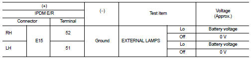
1. Select ŌĆ£EXTERNAL LAMPSŌĆØ of IPDM E/R active test item.
2. With operating the test items, check that the headlamp (LO) is turned ON.
Lo : Headlamp (LO) ON Off : Headlamp (LO) OFF
Is the inspection result normal? YES >> Headlamp (LO) is normal.
NO >> Refer to EXL-47, "Diagnosis Procedure".
Diagnosis Procedure
1.CHECK HEADLAMP (LO) OUTPUT VOLTAGE
 CONSULT-III ACTIVE TEST
1. Turn ignition switch OFF.
2. Disconnect headlamp connector.
3. Turn ignition switch ON.
4. Select ŌĆ£EXTERNAL LAMPSŌĆØ of IPDM E/R active test item.
5. With operating the test items, check voltage between IPDM E/R harness connector and ground.
Is the inspection result normal? YES >> GO TO 2.
NO >> GO TO 3.
2.CHECK HEADLAMP (LO) OPEN CIRCUIT 1. Turn ignition switch OFF.
2. Disconnect IPDM E/R connector.
3. Check continuity between IPDM E/R harness connector and headlamp harness connector.
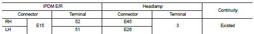
Is the inspection result normal? YES >> Replace headlamp bulb.
NO >> Repair or replace harness.
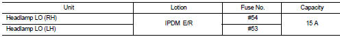
3.CHECK HEADLAMP (LO) FUSE
1. Turn ignition switch OFF.
2. Check that the following fuses are not fusing.
Is the inspection result normal? YES >> Replace IPDM E/R.
NO >> GO TO 4.
4.CHECK HEADLAMP (LO) SHORT CIRCUIT
1. Disconnect IPDM E/R connector.
2. Check continuity between IPDM E/R harness connector and ground.
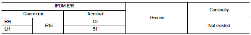
Is the inspection result normal? YES >> Replace the fuse. (Replace IPDM E/R if the fuse is fusing again.) NO >> Repair or replace harness. And then replace the fuse.
 Headlamp (HI) circuit
Component Function Check
1.CHECK HEADLAMP (HI) OPERATION
CONSULT-III ACTIVE TEST
1. Select ŌĆ£EXTERNAL LAMPSŌĆØ of IPDM E/R active test item.
2. With operating the test items, check that the headl ...
 Headlamp ground circuit
Diagnosis Procedure
1.CHECK HEADLAMP GROUND OPEN CIRCUIT
1. Turn ignition switch OFF.
2. Disconnect headlamp connector.
3. Check continuity between headlamp harness connector and ground.
Is the ...
Other materials:
Inspection
LEVEL
ŌĆó Check that the reservoir tank engine coolant level is within the
ŌĆ£MINŌĆØ to ŌĆ£MAXŌĆØ when the engine is cool.
A : MAX
B : MIN
ŌĆó Adjust the engine coolant level if necessary.
LEAKAGE
ŌĆó To check for leakage, apply pressure to the cooling system with the
radiator cap tester ( ...
Timer Display
To provide you with immediate visibility into your vehicle's energy status, the timer display automatically activates for approximately 30 seconds as soon as you place the power switch of your Nissan Leaf in the OFF position.
Charging time
This section ...
Precaution Necessary for Steering Wheel Rotation after Battery Disconnect
NOTE:
ŌĆó Before removing and installing any control units, first turn the ignition
switch to the LOCK position, then disconnect
both battery cables.
ŌĆó After finishing work, confirm that all control unit connectors are connected
properly, then re-connect both
battery cables.
ŌĆó Always us ...
