Nissan Juke Service and Repair Manual : Headlamp (HI) circuit
Component Function Check
1.CHECK HEADLAMP (HI) OPERATION
 CONSULT-III ACTIVE TEST
1. Select “EXTERNAL LAMPS” of IPDM E/R active test item.
2. With operating the test items, check that the headlamp (HI) is turned ON.
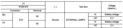
Hi : Headlamp (HI) ON Off : Headlamp (HI) OFF
NOTE
:
ON/OFF is repeated 1 second each.
Is the inspection result normal? YES >> Headlamp (HI) circuit is normal.
NO >> Refer to EXL-45, "Diagnosis Procedure".
Diagnosis Procedure
1.CHECK HEADLAMP (HI) OUTPUT VOLTAGE
 CONSULT-III ACTIVE TEST
1. Turn ignition switch OFF.
2. Disconnect headlamp connector.
3. Turn ignition switch ON.
4. Select “EXTERNAL LAMPS” of IPDM E/R active test item.
5. With operating the test items, check voltage between IPDM E/R harness connector and ground.
Is the inspection result normal? YES >> GO TO 2.
NO >> GO TO 3.
2.CHECK HEADLAMP (HI) OPEN CIRCUIT
1. Turn ignition switch OFF.
2. Disconnect IPDM E/R connector.
3. Check continuity between IPDM E/R harness connector and headlamp harness connector.
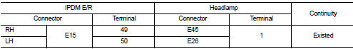
Is the inspection result normal? YES >> Replace headlamp bulb.
NO >> Repair or replace harness.
3.CHECK HEADLAMP (HI) FUSE
1. Turn ignition switch OFF.
2. Check that the following fuses are not fusing.
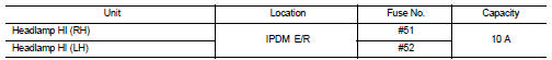
Is the inspection result normal? YES >> Replace IPDM E/R.
NO >> GO TO 4.
4.CHECK HEADLAMP HIGH (HI) SHORT CIRCUIT
1. Disconnect IPDM E/R connector.
2. Check continuity between IPDM E/R harness connector and ground.
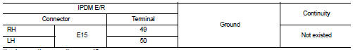
Is the inspection result normal? YES >> Replace the fuse. (Replace IPDM E/R if the fuse is fusing again.) NO >> Repair or replace harness. And then replace the fuse.

 Headlamp (LO) circuit
Component Function Check
1.CHECK HEADLAMP (LO) OPERATION
CONSULT-III ACTIVE TEST
1. Select “EXTERNAL LAMPS” of IPDM E/R active test item.
2. With operating the test items, check that the headl ...
Other materials:
P062f eeprom
DTC Logic
DTC DETECTION LOGIC
DTC CONFIRMATION PROCEDURE
1.PREPARATION BEFORE WORK
If another "DTC CONFIRMATION PROCEDURE" occurs just before, turn ignition
switch OFF and wait for at
least 10 seconds, then perform the next test.
>> GO TO 2.
2.CHECK DTC DETECTION
1. S ...
Back door window glass
Exploded View
1. Back door window glass
2. Spacer
3. Back door window glass holder
4. Back door window glass molding
5. Pivot seal
6. Adhesive
7. Primer
8. Back door outer
9. Back door inner
Unit: mm (in)
: Do not reuse
Removal and Installation
REMOVAL
1. Remove back door lower ...
Types of tires
WARNING
When selecting replacement tires for your Nissan Leaf, it is mandatory to ensure all four tires are of the identical type (e.g., Summer, All-Season, or Snow) and construction. A NISSAN certified LEAF dealer can provide expert guidance regarding the correct tire type, size, spe ...
