Nissan Juke Service and Repair Manual : For side and rollover collision : When SRS is not activated in a collision
CAUTION:
Due to varying models and option levels, not all parts listed in the chart below
apply to all vehicles.
WORK PROCEDURE
1. Before performing any of the following steps, ensure that all vehicle body and structural repairs have been completed.
2. Check the SRS components and the related parts using the following table.
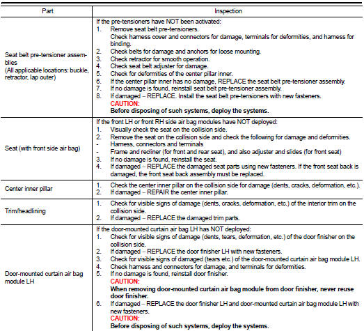
• If the front seat back assembly is damaged, the front seat back assembly must be replaced.
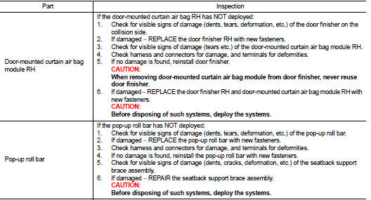
• If the door finisher assembly is damaged, the door finisher assembly and door-mounted curtain air bag module must be replaced.
3. Perform self-diagnosis using CONSULT-III and “AIR BAG” warning lamp. Refer to SRC-12, "Description" for details. Make sure entire SRS operates properly.
4. After the work is completed, perform self-diagnosis to check that no malfunction is detected. Refer to SRC-12, "Description".
SRS INSPECTION (FOR SIDE AND ROLLOVER COLLISION)
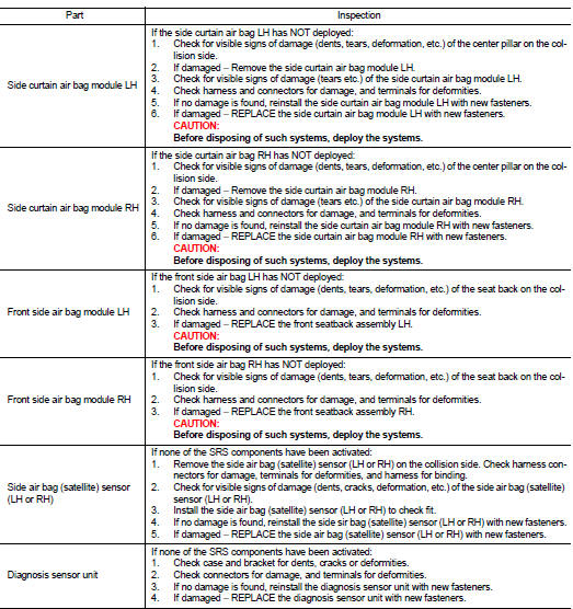
 For side and rollover collision : When SRS is activated in a collision
CAUTION:
Due to varying models and option levels, not all parts listed in the chart below
apply to all vehicles.
WORK PROCEDURE
1. Before performing any of the following steps, ensure that all ...

Other materials:
P181F incomplete calibration
DTC Logic
DTC DETECTION LOGIC
DTC CONFIRMATION PROCEDURE
1.PRECONDITIONING
If “DTC CONFIRMATION PROCEDURE” has been previously conducted, always turn
ignition switch OFF and
wait at least 10 seconds before conducting the next test.
>> GO TO 2.
2.DTC REPRODUCTION PROCEDURE
W ...
EPS warning lamp does not turn on
Description
EPS warning lamp does not turn ON when turning ignition switch ON from OFF.
(Check the illumination of the
EPS warning lamp.)
Diagnosis Procedure
1.CHECK EPS WARNING LAMP
Perform the trouble diagnosis of EPS warning lamp. Refer to STC-26,
"Diagnosis Procedure".
Is t ...
Intelligent Key operation
You can lock or unlock the doors without taking the key out from your pocket
or bag.
When you carry the Intelligent Key with you, you can lock or unlock all doors
by pushing the door handle request switch (driver’s or front passenger’s) A or lift
gate request switchB within the rang ...
