Nissan Juke Service and Repair Manual : For side and rollover collision : When SRS is activated in a collision
CAUTION:
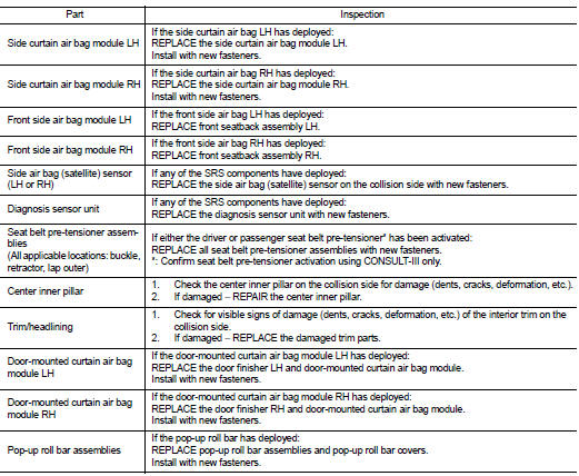
Due to varying models and option levels, not all parts listed in the chart below
apply to all vehicles.
WORK PROCEDURE
1. Before performing any of the following steps, ensure that all vehicle body and structural repairs have been completed.
2. Replace the following components:
• Front seat back assembly (on the side on which side air bag is activated)
• Door finisher (on the side on which door-mounted curtain air bag is
activated)
• Pop-up roll bar assemblies and pop-up roll bar covers
• Side air bag (satellite) sensor LH/RH (on the side on which side air bag is
activated)
• Diagnosis sensor unit
• Seat belt pre-tensioner assemblies
3. Check the SRS components and the related parts using the following table.
Replace any SRS components and the related parts showing visible signs of
damage. (dents, cracks,
deformation, etc.)
4. Perform self-diagnosis using CONSULT-III and “AIR BAG” warning lamp. Refer to
SRC-12, "Description"
for details. Make sure entire SRS operates properly.
5. After the work is completed, perform self-diagnosis to check that no malfunction is detected. Refer to SRC-12, "Description".
SRS INSPECTION (FOR SIDE AND ROLLOVER COLLISION)
 For frontal collision : When SRS is not activated in a collision
CAUTION:
Due to varying models and option levels, not all parts listed in the chart below
apply to all vehicles.
WORK PROCEDURE
1. Before performing any of the following steps, ensure that all ...
 For side and rollover collision : When SRS is not activated in a collision
CAUTION:
Due to varying models and option levels, not all parts listed in the chart below
apply to all vehicles.
WORK PROCEDURE
1. Before performing any of the following steps, ensure that all ...
Other materials:
B1081 seat belt Pre-tensioner RH
DTC Logic
DTC DETECTION LOGIC
DTC CONFIRMATION PROCEDURE
1.CHECK SELF-DIAG RESULT
With CONSULT-III
1. Turn ignition switch ON.
2. Perform “Self Diagnostic Result” mode of “AIR BAG” using CONSULT-III.
Without CONSULT-III
1. Turn ignition switch ON.
2. Check the air bag warning la ...
Drive belt
Checking Drive Belts
WARNING:
Be sure to perform when the engine is stopped.
1. Inspect belts for cracks, fraying, wear and oil. If necessary,
replace.
2. Evaluate manually if the belt is enough tensioned (tension cannot
be measured by way of frequency meter).
CAUTION:
Auto-tensioner must ...
CD/USB memory care and cleaning
CD
• Handle a CD by its edges. Never touch the surface of the disc. Do not bend
the disc.
• Always place the discs in the storage case when they are not being used.
• To clean a disc, wipe the surface from the center to the outer edge using a clean,
soft cloth. Do not wipe the d ...
