Nissan Juke Owners Manual : Eco information
CAUTION
Do not adjust the display controls while driving so that full attention may given to vehicle operation.
The following ECO INFO mode will appear on the display by pushing the ECO information button, then turning the selection dial to scroll through the different screens.
While driving, only one ECO information screen is displayed. The vehicle must be stopped to scroll through the different screens.
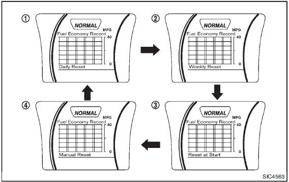
Daily Reset
Records of up to the past 4 days of fuel consumption can be shown on the display.
Weekly Reset
Records of up to the past 4 weeks of each weekŌĆÖs fuel consumption can be shown on the display.
NOTE:
When the clock is not set, the ECO information (daily and weekly) cannot be used.
Reset at Start
Records of up to the past 4 times of each time of ignition switch ON fuel consumption can be shown on the display.
Manual Reset
Records of up to the past 4 times of resetting fuel consumption can be shown on the display.
The displayed ECO INFO can be reset by pushing the ENTER button for longer than 1 second.
 Drive information
While in the Drive mode, push the Drive information button to display elapsed
time, average speed and trip distance. Pressing the Drive information button a second
time will display the G (gravi ...
 Security systems
Your vehicle has two types of security systems, as follows:
ŌĆó Vehicle security system
ŌĆó NISSAN Vehicle Immobilizer System
The security condition will be shown by the security indicator light. ...
Other materials:
SPEED LIMITER MAIN SWITCH
Component Function Check
1.CHECK SPEED LIMITER MAIN SWITCH FUNCTION
With CONSULT-III
1. Turn ignition switch ON.
2. Select ŌĆ£SL MAIN SWŌĆØ in ŌĆ£DATA MONITORŌĆØ mode of ŌĆ£ENGINEŌĆØ using CONSULT-III.
3. Check ŌĆ£SL MAIN SWŌĆØ indication as per the following condition.
Without CONSULT-III
...
Precaution for Supplemental Restraint System (SRS) "AIR BAG" and "SEAT BELT
PRE-TENSIONER"
The Supplemental Restraint System such as ŌĆ£AIR BAGŌĆØ and ŌĆ£SEAT BELT PRE-TENSIONERŌĆØ,
used along
with a front seat belt, helps to reduce the risk or severity of injury to the
driver and front passenger for certain
types of collision. Information necessary to service the system safely is
...
5TH main gear assembly
Removal and Installation
REMOVAL
1. Shift the shifter lever to the 3rd gear position.
2. Disconnect the shifter cable and the selector cable from shifter lever A and
selector lever. Refer to TM-25,
"Removal and Installation".
CAUTION:
Never move shifter lever A and the selector l ...
