Nissan Juke Service and Repair Manual : Drive pinion
Exploded View
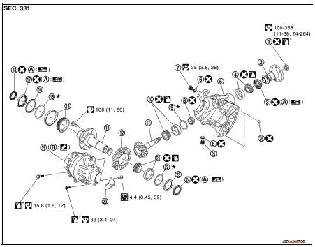
1. Pinion lock nut
2. Companion flange
3. Drive pion oil seal
4. Pinon rear bearing
5. Transfer case
6. Gasket
7. Filler plug
8. Collapsible spacer
9. Drive pinion adjust shim
10. Drive pinion
11. Pinion front bearing
12. Ring gear
13. Ring gear shaft
14. Ring gear bearing (right)
15. Ring gear bearing adjust shim (right)
16. Spacer (right)
17. Transfer case oil seal (right)
18. Drive shaft oil seal
19. Transfer cover
20. Oil defense
21. Ring gear bearing (left)
22. Ring gear bearing adjust shim (left)
23. Spacer (left)
24. Transfer case oil seal (left)
25. Drain plug
26. Dowel pin
A. Oil seal lip
B. Transfer case mounting face
 : N·m (kg-m, ft-lb)
 : Always replace after every
disassembly.
 : Apply gear oil.
 : Apply anti-corrosive oil.
 : Apply multi purpose grease
 : Apply Genuine Liquid Gasket 1215
or equivalent.
 : Select with proper thickness.
Disassembly
1. Remove transfer cover. Refer to DLN-114, "Disassembly".
2. Remove ring gear shaft assembly. Refer to DLN-96, "Disassembly".
3. Remove lock nut from the drive pinion.
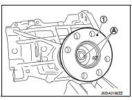
4. Put matching marks (A) on screw ends of companion flange (1) and drive pinion.
CAUTION:
Use paint to avoid scratching the surface.
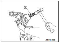
5. Remove companion flange from drive pinion with a puller (A).
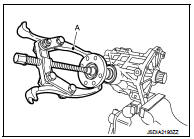
6. Remove drive pinion oil seal from the transfer case with a puller (A) (SST: KV381054S0).
CAUTION:
Never damage transfer case.
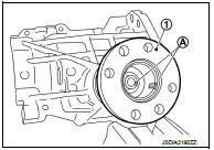
7. Remove drive pinion assembly (1) from transfer case while tapping the drive pinion lightly with a plastic hammer.
CAUTION:
Never drop the drive pinion assembly.
8. Remove collapsible spacer from the drive pinion.
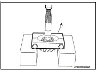
9. Remove inner race of drive pinion bearing (rear side) from transfer case.
10. Remove inner race of drive pinion bearing (front side) from drive pinion with a replacer (A) (commercial service tool).
11. Remove drive pinion adjusting shim from the drive pinion.
12. Perform inspection after disassembly. Refer to DLN-111, "Inspection".
Assembly
1. Select drive pinion adjusting shim. Refer to DLN-98, "Adjustment".
2. Install selected drive pinion adjusting shim to drive pinion.
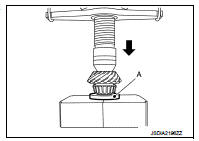
3. Install inner race of drive pinion bearing (front side) to drive pinion with a drift (A) (SST: ST35272000).
CAUTION:
• Never reuse drive pinion bearing (front side).
• Apply gear oil to the drive pinion bearing (front side).
4. Assemble the inner race of drive pinion bearing (rear side) into the transfer case.
CAUTION:
• Never reuse drive pinion bearing (rear side).
• Apply gear oil to the drive pinion bearing (rear side).
5. Install drive pinion oil seal to transfer case with drifts so that it becomes flush with case end surface with the drifts (A and B).
A : Drift (SST: KV38102510) B : Drift (SST: ST30720000)
CAUTION:
• Never reuse oil seal.
• Apply multi-purpose grease onto oil seal lips, and gear oil onto the circumference.
6. Assemble a collapsible spacer onto the drive pinion.
CAUTION:
Never reuse the collapsible spacer.
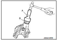
7. Assemble drive pinion assembly into the transfer case, and then install companion flange (1) to drive pinion.
NOTE
:
Align matching marks (A) on the thread edge of companion
flange and drive pinion and install companion flange if drive pinion
is reused.
8. Tap the companion flange (1) with a plastic hammer as far as the lock nut can be tightened.
CAUTION:
Never damage drive pinion oil seal.
9. Apply anti-corrosive oil to the thread and seat of the lock nut, and temporarily tighten lock nut to the drive pinion.
CAUTION:
Never reuse lock nut.
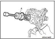
10. Tighten lock nut within the specified torque range with a preload gauge (A) (SST: ST3127S000) so that the drive pinion bearing preload is within standard.
Drive pinion bearing preload : Refer to DLN-117, "Preload Torque".
CAUTION:
• Start the tightening of lock nut from lower limit of the
specified torque. Check the preload every 5° to 10° while
tightening the lock nut.
• Replace the collapsible spacer and tighten it again to adjust if preload exceeds the specified value. Never loosen lock nut to adjust preload.
• After adjustment, rotate the drive pinion back and forth from 2 to 3 times to check for unusual noise, sticking, binding, and so on.
11. Install ring gear shaft assembly. Refer to DLN-97, "Assembly".
12. Install transfer cover. Refer to DLN-114, "Assembly".
13. Check backlash, tooth contact, total preload and companion flange runout. Refer to DLN-98, "Adjustment".
CAUTION:
Measure the total preload without the transfer case oil seal.
Adjustment
About adjusting of drive pinion, refer to DLN-98, "Adjustment".
Inspection
INSPECTION AFTER DISASSEMBLY
Check items below. If necessary, replace them with new ones.
Gear and Shaft Check gear face and shaft for wear, cracks, damage, and seizure.
CAUTION:
Replace ring gear and drive pinion as a set (hypoid gear set) if any malfunction
is detected on the ring
gear or drive pinion.
Bearing
Check for seizure, peeling, wear, corrosion, sticking, unusual noise, roughness
in hand turning, and other
damage.
CAUTION:
Always replace inner race and outer race as a pair when replacing the bearing.
Shim
Check for seizure, damage, and unusual wear.
Case
Check the bearing mounting surface for wear, cracks and damages.
CAUTION
:
Replace transfer case and transfer cover as a set if any malfunction is detected
on transfer case or
transfer cover.
 Ring gear shaft
Exploded View
1. Pinion lock nut
2. Companion flange
3. Drive pion oil seal
4. Pinon rear bearing
5. Transfer case
6. Gasket
7. Filler plug
8. Collapsible spacer
9. Drive pinion adjus ...
 Transfer case
Exploded View
1. Pinion lock nut
2. Companion flange
3. Drive pion oil seal
4. Pinon rear bearing
5. Transfer case
6. Gasket
7. Filler plug
8. Collapsible spacer
9. Drive pinion adjus ...
Other materials:
Headlining
Exploded View
LHD models
1. Headlining assembly
2. Assist grip clip
3. Rear assist grip RH
4. Front assist grip RH
5. Sun visor assembly RH
6. Sun visor cover RH
7. Sun visor cover LH
8. Sun visor assembly LH
9. Rear assist grip LH
10. Headlining clip
11. Sun visor holder RH
1 ...
Steering Assist limitations
WARNING
In the following situations, the front-facing camera may fail to identify lane markers accurately or misinterpret road features, which may result in the Steering Assist system failing to operate as intended:
When navigating roads with confusing, ...
Reporting safety defects
For USA
If you believe that your vehicle has a defect which could cause a crash or could
cause injury or death, you should immediately inform the National Highway Traffic
Safety Administration (NHTSA) in addition to notifying NISSAN.
If NHTSA receives similar complaints, it may open an investi ...
