Nissan Juke Service and Repair Manual : Transfer case
Exploded View
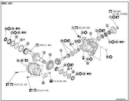
1. Pinion lock nut
2. Companion flange
3. Drive pion oil seal
4. Pinon rear bearing
5. Transfer case
6. Gasket
7. Filler plug
8. Collapsible spacer
9. Drive pinion adjust shim
10. Drive pinion
11. Pinion front bearing
12. Ring gear
13. Ring gear shaft
14. Ring gear bearing (right)
15. Ring gear bearing adjust shim (right)
16. Spacer (right)
17. Transfer case oil seal (right)
18. Drive shaft oil seal
19. Transfer cover
20. Oil defense
21. Ring gear bearing (left)
22. Ring gear bearing adjust shim (left)
23. Spacer (left)
24. Transfer case oil seal (left)
25. Drain plug
26. Dowel pin
A. Oil seal lip
B. Transfer case mounting face
 : N·m (kg-m, ft-lb)
 : Always replace after every
disassembly.
 : Apply gear oil.
 : Apply anti-corrosive oil.
 : Apply multi purpose grease
 : Apply Genuine Liquid Gasket 1215
or equivalent.
 : Select with proper thickness.
Disassembly
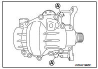
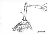
1. Remove transfer cover mounting bolts.
2. Lightly tap (A) position of transfer cover with a plastic hammer to remove transfer cover.
3. Remove ring gear shaft assembly. Refer to DLN-96, "Disassembly",
4. Tap the outer race of drive pinion bearing from transfer case with a brass rod to remove outer race of drive pinion bearing (front side and rear side).
CAUTION:
Never damage transfer case.
5. Remove dowel pin.
CAUTION:
Never remove dowel pin, if it is not necessary to replace.
6. Remove the filler plug and drain plug from the transfer case, and then remove each gasket.
7. Remove oil defense from transfer cover.
8. Perform inspection after disassembly. Refer to DLN-116, "Inspection".
Assembly
1. Install the oil defense to transfer cover.
2. Install gaskets onto filler plug and drain plug and install them into transfer case.
CAUTION:
• Never reuse gaskets.
• Install filler plug after oil is filled.
3. Install the dowel pin to transfer case.
CAUTION:
Never reuse the dowel pin.
4. Install outer race of drive pinion bearing (front side) to the transfer case with drift (A) (SST: ST17130000).
CAUTION:
• Never reuse drive pinion bearing (front side).
• Apply gear oil to the drive pinion bearing (front side)
5. Install outer race of drive pinion bearing (rear side) to transfer case with a drift (A) (SST: ST33230000).
CAUTION:
• Never reuse drive pinion bearing (rear side).
• Apply gear oil to the drive pinion bearing (rear side).
6. Install drive pinion assembly to transfer case. Refer to DLN-110, "Assembly".
7. Install ring gear shaft assembly to transfer case. Refer to DLN- 97, "Assembly".
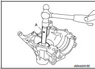
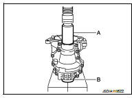
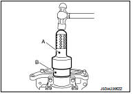
8. Set the drifts (A and B) to right and left side spacers individually.
Compress ring gear shaft assembly and ring gear bearing to install transfer cover to transfer case.
A : Drift (commercial service tool) B : Drift (commercial service tool)
CAUTION:
• Clean the mounting surface of transfer case and transfer
cover to degrease sufficiently.
• Never apply gasket fluid on the mounting surface.
• The drift shall be placed on the center of the spacers.
• The pressure shall be as low as to install ring gear shaft assembly into transfer case. The maximum pressure shall be 10 kN (1 ton, 1.0 Imp ton).
• If the adjusting shims and spacers are installed by tapping, the transfer cover may be damaged.
Avoid tapping.
9. Check backlash, tooth contact, total preload and companion flange runout. Refer to DLN-98, "Adjustment".
CAUTION:
Measure the total preload without the transfer case oil seals.
10. Remove transfer cover. Refer to DLN-114, "Disassembly".
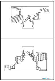
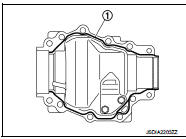
11. Apply liquid gasket (1) to mating surface of rear cover.
CAUTION:
• Remove old gasket adhering to the mounting surfaces.
Also remove any moisture, oil, or foreign material adhering to the mounting surfaces.
• Overlap both ends of the bead for at least 3 mm (0.12 in).
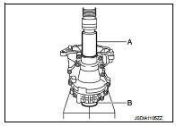
12. Set the drifts (A and B) to right and left side spacers individually.
Compress ring gear shaft assembly and ring gear bearing to install transfer cover to transfer case.
A : Drift (commercial service tool) B : Drift (commercial service tool)
CAUTION:
• Immediately install after applying gasket.
• The drift shall be placed on the center of the spacers.
• The pressure shall be as low as to install ring gear shaft assembly into transfer case. The maximum pressure shall be 10 kN (1 ton, 1.0 Imp ton).
• If the adjusting shims and spacers are installed by tapping, the transfer cover may be damaged.
Avoid tapping.
13. Tighten rear cover mounting bolts to the specified torque.
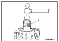
14. Install transfer case oil seal (right side) until it becomes flush with ring gear shaft end, using the drifts (A and B).
A : Drift (SST: ST30720000) B : Drift (SST: ST19820000)
CAUTION:
• Never reuse oil seals.
• When installing, do not incline oil seals.
• Apply multi-purpose grease onto oil seal lips, and gear oil onto the circumference of oil seal.
• Immediately install after installing transfer cover.
15. Install transfer case oil seal (left side) until it becomes flush with ring gear shaft end, using the drift (A) (SST: KV40100620).
CAUTION:
• Never reuse oil seals.
• When installing, do not incline oil seals.
• Apply multi-purpose grease onto oil seal lips, and gear oil onto the circumference of oil seal.
• Immediately install after installing transfer cover.
• After installing oil seal, immediately wipe out gasket squeezed out inward of transfer case.
Inspection
INSPECTION AFTER DISASSEMBLY
Check items below. If necessary, replace them with new ones.
Case
Check the bearing mounting surface for wear, cracks and damages.
CAUTION:
Replace transfer case and transfer cover as a set if any malfunction is detected
on transfer case or
transfer cover.
 Drive pinion
Exploded View
1. Pinion lock nut
2. Companion flange
3. Drive pion oil seal
4. Pinon rear bearing
5. Transfer case
6. Gasket
7. Filler plug
8. Collapsible spacer
9. Drive pinion adjus ...

Other materials:
Diagnosis system (BCM)
Common item
COMMON ITEM : CONSULT-III Function (BCM - COMMON ITEM)
APPLICATION ITEM
CONSULT-III performs the following functions via CAN communication with BCM.
SYSTEM APPLICATION
BCM can perform the following functions for each system.
NOTE:
It can perform the diagnosis modes except the ...
P0403 EGR volume control valve
DTC Logic
DTC DETECTION LOGIC
Diagnosis Procedure
1.CHECK EGR VOLUME CONTROL VALVE CONTROL CIRCUIT
1. Turn ignition switch OFF.
2. Disconnect EGR volume control valve harness connector and ECM harness
connector.
3. Check the continuity between EGR volume control valve terminal harness
co ...
Gas station information
FUEL RECOMMENDATION:
NISSAN recommends the use of unleaded premium gasoline with an octane rating
of at least 91 AKI (Anti-Knock Index) number (Research octane number 96).
If unleaded premium gasoline is not available, you may use unleaded regular gasoline
with an octane rating of at least 87 ...
