Nissan Juke Service and Repair Manual : Ring gear shaft
Exploded View
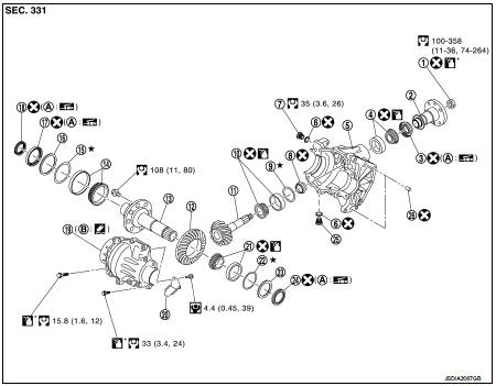
1. Pinion lock nut
2. Companion flange
3. Drive pion oil seal
4. Pinon rear bearing
5. Transfer case
6. Gasket
7. Filler plug
8. Collapsible spacer
9. Drive pinion adjust shim
10. Drive pinion
11. Pinion front bearing
12. Ring gear
13. Ring gear shaft
14. Ring gear bearing (right)
15. Ring gear bearing adjust shim (right)
16. Spacer (right)
17. Transfer case oil seal (right)
18. Drive shaft oil seal
19. Transfer cover
20. Oil defense
21. Ring gear bearing (left)
22. Ring gear bearing adjust shim (left)
23. Spacer (left)
24. Transfer case oil seal (left)
25. Drain plug
26. Dowel pin
A. Oil seal lip
B. Transfer case mounting face
 : N·m (kg-m, ft-lb)
 : Always replace after every
disassembly.
 : Apply gear oil.
 : Apply anti-corrosive oil.
 : Apply multi purpose grease
 : Apply Genuine Liquid Gasket 1215
or equivalent.
 : Select with proper thickness.
Disassembly
1. Remove transfer cover. Refer to DLN-114, "Disassembly".
2. Remove transfer case oil seal (right and left side).
3. Remove ring gear shaft assembly from transfer case.
4. Remove ring gear bearing outer race (right and left side) from ring gear shaft assembly.
5. Remove ring gear bearing adjust shim (right and left side) from ring gear shaft assembly.
6. Remove spacer (right and left side) from ring gear shaft assembly.
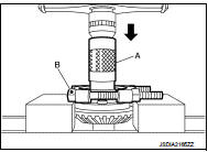
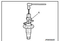
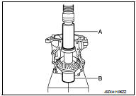
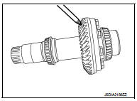
7. Remove gear ring bearing inner race (left side) from ring gear shaft with the drift (A) and a replacer (B).
A : Drift (SST:ST33200000) B : Replacer (commercial service tool)
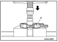
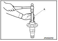
8. Remove gear ring bearing inner race (right side) from ring gear shaft with a replacer (A) (commercial service tool).
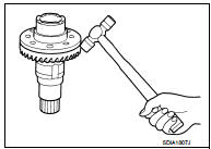
9. Remove the ring gear mounting bolts.
10. Lightly tap adapter case with a plastic hammer to remove drive gear from ring gear shaft.
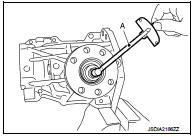
11. Remove drive shaft oil seal from the gear ring with a puller (A) (SST: KV381054S0).
12. Perform inspection after disassembly. Refer to DLN-107, "Inspection".
Assembly
1. Select ring gear bearing adjust shim (right and left side). Refer to DLN-98, "Adjustment".
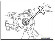
2. Install drive shaft oil seal until it becomes flush with ring gear shaft end, using the drift (A) (SST: ST33230000).
CAUTION:
• Never reuse the oil seal.
• When installing, never incline oil seal.
• Apply multi-purpose grease to oil seal lip.
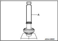
3. Install the gear ring bearing inner race (right side) to gear ring with the drift (A) (commercial service tool).
CAUTION:
• Never reuse the ring gear bearing.
• Apply gear oil to gear ring bearing inner race.
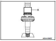
Install the gear ring bearing inner race (left side) to gear ring with the drift (A) (commercial service tool).
CAUTION:
• Never reuse the ring gear bearing.
• Apply gear oil to gear ring bearing inner race.
5. Install spacer (right and left side) to ring gear shaft assembly.
6. Install selected ring gear bearing adjust shim (right and left side) to ring gear shaft assembly.
7. Install ring gear bearing outer race (right and left side) to ring gear shaft assembly.
CAUTION:
• Never reuse the ring gear bearing.
• Apply gear oil to gear ring bearing outer race.
8. Set the drifts (A and B) to right and left side spacers individually.
Compress ring gear shaft assembly and ring gear bearing to install ring gear shaft assembly to transfer case.
A : Drift (commercial service tool) B : Drift (commercial service tool)
CAUTION:
• The drift shall be placed on the center of the spacers.
• The pressure shall be as low as to install ring gear shaft assembly into transfer case. The maximum pressure shall be 10 kN (1 ton, 1.0 Imp ton).
• If the adjusting shims and spacers are installed by tapping, the transfer case may be damaged. Avoid tapping.
9. Install transfer cover.Refer to DLN-114, "Assembly".
10. Check backlash, tooth contact, total preload and companion flange runout. Refer to DLN-98, "Adjustment".
CAUTION:
Measure the total preload without the adapter case oil seal.
11. Install the transfer case oil seal (left and right side). Refer to DLN-114, "Assembly".
Adjustment
Adjusting shim selection
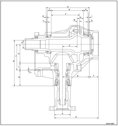
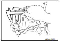
Measurement point
1. Transfer assembly
Ring gear bearing adjusting shim (right side) 1. Measure the dimensions of each measuring point with the following procedure: Dimension “A” measurement
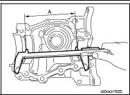
• Measure dimension (A) of transfer case with a pair of vernier calipers. Refer to “Measuring point”.
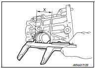
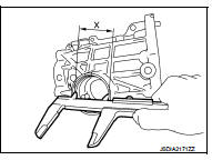
Dimension “X” measurement • Measure the diameter (X) of transfer case with a pair of vernier calipers. Refer to “Measuring point”.
Dimension “Y” measurement • Measure dimension (Y) of transfer case with a pair of vernier calipers. Refer to “Measuring point”.
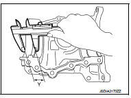
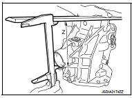
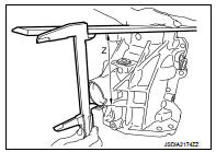
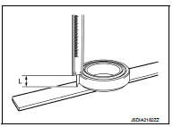
Dimension “Z” measurement • Measure dimension (Z) of transfer case with a pair of vernier calipers and straightedge. Refer to “Measuring point”.
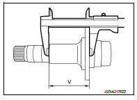
Dimension “V” measurement • Measure dimension (V) of ring gear shaft with a pair of vernier calipers. Refer to “Measuring point”.
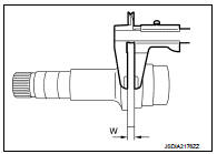
Dimension “W” measurement • Measure dimension (W) of ring gear shaft with a pair of vernier calipers. Refer to “Measuring point”.
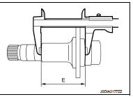
Dimension “E” measurement • Measure dimension (E) of ring gear shaft with a pair of vernier calipers. Refer to “Measuring point”.
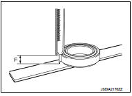
Dimension “F” measurement • Measure dimension (F) from outer race edge surface of ring gear shaft bearing (right side) to inner race edge surface with a pair of vernier calipers and straightedge. Refer to “Measuring point”.
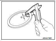
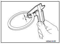
Dimension “G” measurement • Measure thickness (G) of spacer (right side) with a pair of vernier calipers. Refer to “Measuring point”.
2. Calculate dimension “B” by the formula below.
B = Z − Y − (X × 0.5)
3. Calculate dimension “D” by the formula below.
D = E − V + W
4. Calculate the thickness of the ring gear bearing adjusting shim (right side) “T1” by the formula below.
T1 = A − B + C + D − E − F − G + 0.045 mm (0.0018 in)
NOTE
:
Calculate dimension “C” as 56.0 mm (2.20 in)
5. Select ring gear bearing adjusting shim (right side).
CAUTION:
• Only one adjusting shim can be selected.
• Select the closest one, favoring thicker over thinner when necessary if no adjusting shim with the calculated value is available.
Ring gear bearing adjusting shim (right side) 1. Measure the dimensions of each measuring point with the following procedure: Dimension “X” measurement • Measure the diameter (X) of transfer case with a pair of vernier calipers. Refer to “Measuring point”.
Dimension “Y” measurement • Measure dimension (Y) of transfer case with a pair of vernier calipers. Refer to “Measuring point”.
Dimension “Z” measurement • Measure dimension (Z) of transfer case with a pair of vernier calipers and straightedge. Refer to “Measuring point”.
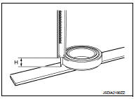
Dimension “H” measurement • Measure dimension (H) from outer race edge surface of ring gear shaft bearing (left side) to inner race edge surface with a pair of vernier calipers and straightedge. Refer to “Measuring point”.
Dimension “I” measurement • Measure thickness (I) of spacer (left side) with a pair of vernier calipers. Refer to “Measuring point”.
2. Calculate dimension “B” by the formula below.
B = Z − Y − (X × 0.5)
3. Calculate dimension “D” by the formula below.
D = E − V + W
4. Calculate the thickness of the ring gear bearing adjusting shim (left side) “T2” by the formula below.
T2 = B − C − D − H − I + 0.045 mm (0.0018 in)
NOTE
:
Calculate dimension “C” as 56.0 mm (2.20 in)
5. Select ring gear bearing adjusting shim (left side).
CAUTION:
• Only one adjusting shim can be selected.
• Select the closest one, favoring thicker over thinner when necessary if no adjusting shim with the calculated value is available.
Drive pinion adjusting shim 1. Measure the dimensions of each measuring point with the following procedure: Dimension “L” measurement • Measure dimension (L) from outer race edge surface of pinion rear bearing to inner race edge surface with a pair of vernier calipers and straightedge. Refer to “Measuring point”.
Dimension “Q” measurement • Measure dimension (Q) of transfer case with a pair of vernier calipers and straightedge. Refer to “Measuring point”.
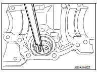
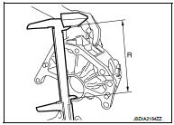
Dimension “R” measurement • Measure dimension (R) of transfer case with a pair of vernier calipers and straightedge. Refer to “Measuring point”.
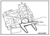
Dimension “S” measurement • Measure the diameter (S) of transfer case with a pair of vernier calipers. Refer to “Measuring point”.
2. Calculate dimension “J” by the formula below.
J = Q − R − (S × 0.5)
3. Calculate the thickness of the drive pinion adjusting shim “T3” by the formula below.
T3 = J − K − L
NOTE
:
Calculate dimension “K” as 70.85 mm (2.7894 in)
4. Select drive pinion adjusting shim.
CAUTION:
• Only one adjusting shim can be selected.
• Select the closest one, favoring thicker over thinner when necessary if no adjusting shim with the calculated value is available.
DRIVE PINION BEARING PRELOAD
1. Remove ring gear shaft assembly from the transfer case. Refer to DLN-96, "Disassembly".
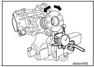
2. Rotate the companion flange back and forth from 2 to 3 times to check for unusual noise, binding, sticking, and so on.
3. Rotate the companion flange at least 20 times to check for smooth operation of the bearing.
4. Measure the drive pinion bearing preload with a preload gauge (A) (SST: ST3127S000).
Drive pinion bearing preload : Refer to DLN-117, "Preload Torque".
CAUTION:
• Each rotational part should rotate smoothly with the specified
gear oil.
• Disassemble the drive pinion assembly to check and adjust each part if outside the standard.
TOTAL PRELOAD
1. Measure drive pinion bearing preload (P1). Refer to DLN-117, "Preload Torque".
CAUTION:
Check that the drive pinion bearing preload is within the standard.
2. Assemble the ring gear shaft assembly to the transfer case. Refer to DLN-97,
"Assembly"
3. Install transfer cover. Refer to DLN-114, "Assembly".
4. Rotate the companion flange at least 20 times to check for smooth operation of the bearing.
5. Measure the total preload with a preload gauge (A) (SST: ST3127S000).
Total preload :Refer to DLN-117, "Preload Torque".
CAUTION:
• Each rotational part should rotate smoothly with the specified
gear oil.
• Disassemble the transfer assembly to check and adjust each part if outside the standard. Measure it with the transfer case oil seals removed when measuring total preload after disassembly. Then install transfer case oil seals.
BACKLASH
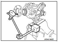
1. Install the bolt (A) to the companion flange.
2. Fit a dial indicator onto the bolt.
3. Measure the circumference backlash of the companion flange.
Backlash : Refer to DLN-117, "Backlash".
4. If outside the standard, disassemble the transfer assembly to check and adjust each part.
TOOTH CONTACT
1. Remove transfer cover. Refer to DLN-114, "Disassembly".
2. Remove ring gear shaft assembly from transfer case. Then apply red lead onto the ring gear. Refer to DLN-96, "Disassembly".
CAUTION:
Apply red lead to both faces of 3 to 4 gears at 4 locations
evenly spaced on the ring gear.
3. Assemble the ring gear shaft assembly to the transfer case.
Refer to DLN-97, "Assembly".
4. Install transfer cover. Refer to DLN-114, "Assembly".
5. Rotate the companion flange back and forth several times.
6. Remove ring gear shaft assembly from transfer case. Then check drive pinion to ring gear tooth contact
Tooth Contact Judgment Guide
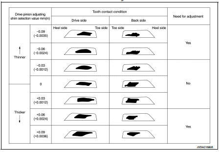
7. Follow the procedure below to adjust pinion height (dimension X) if tooth contact is improper.
CAUTION:
If no adjusting shim with the calculated value is available,
select the thicker and closest one
.
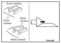
• Thicken the drive pinion adjusting shim to move the drive pinion closer to the ring gear in case of face contact or heel contact.
CAUTION:
Only one adjusting shim can be selected.
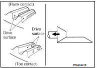
• Thin the drive pinion adjusting shim to move the drive pinion farther from the ring gear in case of flank contact or toe contact.
CAUTION:
Only one adjusting shim can be selected.
8. Assemble the plug to the transfer case.
CAUTION:
• Remove old gasket on mounting surface, then remove
any moisture, oil, and foreign material on the application
and mounting surfaces.
• Apply liquid gasket to the thread, and tighten to the specified torque when installing plug.
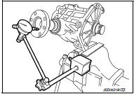
COMPANION FLANGE RUNOUT
1. Fit a dial indicator onto the companion flange face (inner side of the propeller shaft bolt holes).
2. Rotate the companion flange to check for runout.
Companion flange runout : Refer to DLN-117, "Companion Flange Runout".
3. Fit a test indicator to the inner side of the companion flange (socket diameter).
4. Rotate the companion flange to check for runout.
Companion flange runout : Refer to DLN-117, "Companion Flange Runout".
5. Follow the procedure below to adjust if runout value is outside the repair limit.
CAUTION:
Replace collapsible spacer to check and adjust each part
when companion flange is adjusted or replaced.
a. Check for runout while changing the phase between companion flange and drive pinion in 90° steps. Then search for the minimum point.
b. Replace companion flange if runout value is still outside the limit after the phase has been changed.
c. Adjust assembly status of the drive pinion bearings and drive pinion, or replace drive pinion bearings if runout is outside the standard after the companion flange is replaced.
Inspection
INSPECTION AFTER DISASSEMBLY
Check items below. If necessary, replace them with new ones.
Gear and Shaft
Check gear face and shaft for wear, cracks, damage, and seizure.
CAUTION:
Replace ring gear and drive pinion as a set (hypoid gear set) if any malfunction
is detected on the ring
gear or drive pinion.
Bearing
Check for seizure, peeling, wear, corrosion, sticking, unusual noise, roughness
in hand turning, and other
damage.
CAUTION:
Always replace inner race and outer race as a pair when replacing the bearing.
Shim
Check for seizure, damage, and unusual wear.
Case
Check the bearing mounting surface for wear, cracks and damages.
CAUTION:
Replace transfer case and transfer cover as a set if any malfunction is detected
on transfer case or
transfer cover.

 Drive pinion
Exploded View
1. Pinion lock nut
2. Companion flange
3. Drive pion oil seal
4. Pinon rear bearing
5. Transfer case
6. Gasket
7. Filler plug
8. Collapsible spacer
9. Drive pinion adjus ...
Other materials:
Engine stand setting
Setting
NOTE:
Explained here is how to disassemble with engine stand supporting transaxle
surface. When using different
type of engine stand, note with difference in steps and etc.
1. Remove the engine and the transaxle assembly from the vehicle, and separate
the transaxle from the
engine ...
Steering Assist
WARNING
Failure to strictly adhere to these safety warnings and operational guidelines for the Steering Assist system in your Nissan Leaf could lead to a serious accident, personal injury, or death.
The Steering Assist feature is intended solely as a driver-assistance aid; it is ...
Headlamp aiming system (manual)
Component Inspection
1.CHECK HEADLAMP AIMING SWITCH
1. Remove headlamp aiming switch.
2. Check resistance among each headlamp aiming switch terminal.
Is the inspection result normal?
YES >> Headlamp aiming switch is normal.
NO >> Replace the headlamp aiming switch.
...
