Nissan Juke Service and Repair Manual : Clutch pedal position switch
Component Function Check
1.CHECK CLUTCH PEDAL POSITION SWITCH FUNCTION
 With CONSULT-III
1. Turn ignition switch ON.
2. Select ÔÇťENGINEÔÇŁ using CONSULT-III.
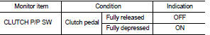
3. Select ÔÇťCLUTCH P/P SWÔÇŁ in ÔÇťDATA MONITORÔÇŁ mode.
4. Check ÔÇťCLUTCH P/P SWÔÇŁ indication under the following conditions.
 Without CONSULT-III
1. Turn ignition switch ON.
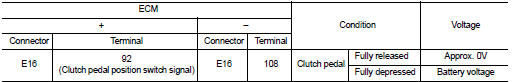
2. Check the voltage between ECM harness connector and ground.
Is the inspection result normal? YES >> INSPECTION END
NO >> Go to EC-771, "Diagnosis Procedure".
Diagnosis Procedure
1.CHECK CLUTCH PEDAL POSITION SWITCH GROUND CIRCUIT FOR OPEN AND SHORT
1. Turn ignition switch OFF.
2. Disconnect clutch pedal position switch harness connector.
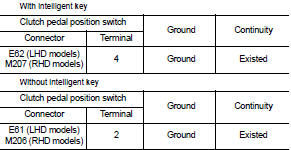
3. Check the continuity between clutch pedal position switch harness connector and ground.
4. Also check harness for short to power.
Is the inspection result normal? YES >> GO TO 2.
NO >> Repair open circuit or short to power in harness or connectors.
2.CHECK CLUTCH PEDAL POSITION SWITCH INPUT SIGNAL CIRCUIT FOR OPEN AND SHORT
1. Disconnect ECM harness connector.
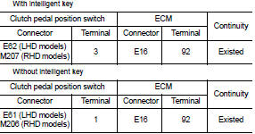
2. Check the continuity between clutch pedal position switch harness connector and ECM harness connector.
3. Also check harness for short to ground and short to power.
Is the inspection result normal? YES >> GO TO 3.
NO >> Repair open circuit or short to ground or short to power in harness or connectors.
3.CHECK CLUTCH PEDAL POSITION SWITCH
Refer to EC-772, "Component Inspection".
Is the inspection result normal? YES >> GO TO 4.
NO >> Replace clutch pedal position switch.
4.CHECK INTERMITTENT INCIDENT
Refer to GI-42, "Intermittent Incident".
>> INSPECTION END
Component Inspection
1.CHECK CLUTCH PEDAL POSITION SWITCH-I
1. Turn ignition switch OFF.
2. Disconnect clutch pedal position switch harness connector.
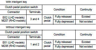
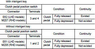
3. Check the continuity between clutch pedal position switch terminals under the following conditions.
Is the inspection result normal? YES >> INSPECTION END
NO >> GO TO 2.
2.CHECK CLUTCH PEDAL POSITION SWITCH-II
1. Adjust clutch pedal position switch installation. Refer to CL-7, "Inspection and Adjustment".
2. Check the continuity between clutch pedal position switch terminals under the following conditions.
Is the inspection result normal? YES >> INSPECTION END
NO >> Replace clutch pedal position switch.
 ASCD main switch
Component Function Check
1.CHECK ASCD MAIN SWITCH FUNCTION
With CONSULT-III
1. Turn ignition switch ON.
2. Select ÔÇťENGINEÔÇŁ using CONSULT-III.
3. Select ÔÇťMAIN SWÔÇŁ in ÔÇťDATA MONITORÔÇŁ mod ...
 Cooling fan
Component Function Check
1.CHECK COOLING FAN FUNCTION
With CONSULT-III
1. Turn ignition switch ON.
2. Perform ÔÇťCOOLING FANÔÇŁ in ÔÇťACTIVE TESTÔÇŁ mode with CONSULT-III.
3. Touch ÔÇťLOWÔÇŁ and ...
Other materials:
Front drive shaft boot
Exploded View
LEFT SIDE
1. Circular clip
2. Dust shield
3. Housing assembly
4. Boot band
5. Boot
6. Damper band
7. Dynamic damper
8. Circular clip
9. Joint sub-assembly
: Wheel side
: Fill NISSAN Genuine grease or
equivalent.
: Always replace after every
disassembly.
RIGHT ...
Trouble diagnosis - specification
value
Description
The specification (SP) value indicates the tolerance of the value that is
displayed in ÔÇťSPECÔÇŁ of ÔÇťDATA MONITORÔÇŁ
mode of CONSULT-III during normal operation of the Engine Control System. When
the value in ÔÇťSPECÔÇŁ
of ÔÇťDATA MONITORÔÇŁ mode is within the SP value, the En ...
P17B4 low brake solenoid
DTC Logic
DTC DETECTION LOGIC
DTC CONFIRMATION PROCEDURE
1.PREPARATION BEFORE WORK
If another "DTC CONFIRMATION PROCEDURE" occurs just before, turn ignition
switch OFF and wait for at
least 10 seconds, then perform the next test.
>> GO TO 2.
2.CHECK DTC DETECTION
1. S ...
