Nissan Juke Service and Repair Manual : ASCD main switch
Component Function Check
1.CHECK ASCD MAIN SWITCH FUNCTION
 With CONSULT-III
1. Turn ignition switch ON.
2. Select ŌĆ£ENGINEŌĆØ using CONSULT-III.
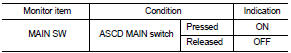
3. Select ŌĆ£MAIN SWŌĆØ in ŌĆ£DATA MONITORŌĆØ mode.
4. Check ŌĆ£MAIN SWŌĆØ indication under the following condition.
 Without CONSULT-III
1. Turn ignition switch ON.
2. Check the voltage between ECM harness connector and ground under the following conditions.
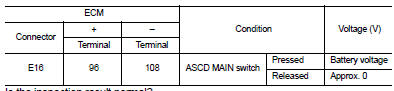
Is the inspection result normal? YES >> INSPECTION END
NO >> Go to EC-768, "Diagnosis Procedure".
Diagnosis Procedure
1.CHECK GROUND CONNECTION
1. Turn ignition switch OFF.
2. Check ground connection E21 and E38. Refer to Ground Inspection in GI-44, "Circuit Inspection".
Is the inspection result normal? YES >> GO TO 2.
NO >> Repair or replace ground connection.
2.CHECK ASCD MAIN SWITCH POWER SUPPLY CIRCUIT
1. Turn ignition switch OFF.
2. Disconnect combination switch (spiral cable) harness connector.
3. Turn ignition switch ON.
4. Check the voltage between combination switch harness connector and ground.
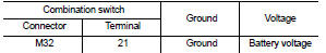
5. Also check harness for short to ground and short to power.
Is the inspection result normal? YES >> GO TO 4.
NO >> GO TO 3.
3.DETECT MALFUNCTIONING PART
Check the following.
ŌĆó 10 A fuse (No. 3)
ŌĆó Combination switch (spiral cable)
ŌĆó Harness for open and short between combination switch and fuse
>> Repair open circuit, short to ground or short to power in harness or connectors.
4.CHECK ASCD MAIN SWITCH INPUT SIGNAL CIRCUIT FOR OPEN AND SHORT
1. Disconnect ECM harness connector.
2. Check the continuity between ECM harness connector and combination switch harness connector.

3. Also check harness for short to ground and short to power.
Is the inspection result normal? YES >> GO TO 6.
NO >> GO TO 5.
5.DETECT MALFUNCTIONING PART
Check the following.
ŌĆó Harness connectors E105, M77 ŌĆó Combination switch (spiral cable) ŌĆó Harness for open and short between ECM and combination switch
>> Repair open circuit, short to ground or short to power in harness or connectors.
6.CHECK ASCD STEERING SWITCH
Refer to EC-769, "Component Inspection (ASCD STEERING SWITCH)".
Is the inspection result normal? YES >> GO TO 7.
NO >> Replace ASCD steering switch.
7.CHECK INTERMITTENT INCIDENT
1. Refer to GI-42, "Intermittent Incident".
Is the inspection result normal? YES >> Replace IPDM E/R.
NO >> Repair open circuit, short to ground or short to power in harness or connectors.
Component Inspection (ASCD STEERING SWITCH)
1.CHECK ASCD STEERING SWITCH-I
1. Turn ignition switch OFF.
2. Disconnect combination switch (spiral cable) harness connector.
3. Check the continuity between combination switch harness connector terminals under the following condition.
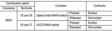
Is the inspection result normal? YES >> GO TO 2.
NO >> Replace ASCD steering switch.
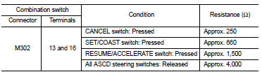
2.CHECK ASCD STEERING SWITCH-II
Check resistance between combination switch (spiral cable) harness connector terminals under the following conditions.
Is the inspection result normal? YES >> INSPECTION END
NO >> Replace ASCD steering switch.
 ASCD indicator
Component Function Check
1.CHECK ASCD INDICATOR FUNCTION
Check ASCD indicator under the following conditions.
Is the inspection result normal?
YES >> INSPECTION END
NO >> Go to EC-7 ...
 Clutch pedal position switch
Component Function Check
1.CHECK CLUTCH PEDAL POSITION SWITCH FUNCTION
With CONSULT-III
1. Turn ignition switch ON.
2. Select ŌĆ£ENGINEŌĆØ using CONSULT-III.
3. Select ŌĆ£CLUTCH P/P SWŌĆØ in ŌĆ£D ...
Other materials:
B27B0 A/C auto AMP.
DTC Logic
DTC DETECTION LOGIC
NOTE:
ŌĆó If DTC is displayed along with DTC U1000, first perform the trouble diagnosis
for DTC U1000. Refer to HAC-
141, "DTC Logic".
ŌĆó If DTC is displayed along with DTC U1010, first perform the trouble diagnosis
for DTC U1010. HAC-142,
"DTC ...
B1068, B1073 passenger air bag module
DTC Logic
DTC DETECTION LOGIC
DTC CONFIRMATION PROCEDURE
1.CHECK SELF-DIAG RESULT
With CONSULT-III
1. Turn ignition switch ON.
2. Perform ŌĆ£Self Diagnostic ResultŌĆØ mode of ŌĆ£AIR BAGŌĆØ using CONSULT-III.
Without CONSULT-III
1. Turn ignition switch ON.
2. Check the air bag warning la ...
Front-seat Active Head Restraints
The Active Head Restraint moves forward utilizing the force that the seatback
receives from the occupant in a rear-end collision. The movement of the head restraint
helps support the occupantŌĆÖs head by reducing its backward movement and helping
absorb some of the forces that may lead to wh ...
