Nissan Juke Service and Repair Manual : B1042, B1043, B1044, B1045, B1046, B1047 diagnosis sensor unit
DTC Logic
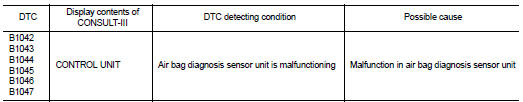
DTC DETECTION LOGIC
DTC CONFIRMATION PROCEDURE
1.CHECK SELF-DIAG RESULT
 With CONSULT-III
1. Turn ignition switch ON.
2. Perform ŌĆ£Self Diagnostic ResultŌĆØ mode of ŌĆ£AIR BAGŌĆØ using CONSULT-III.
 Without CONSULT-III
1. Turn ignition switch ON.
2. Check the air bag warning lamp status. Refer to SRC-12, "On Board Diagnosis Function".
NOTE
:
SRS does not enter the diagnosis mode if no malfunction is detected in the user
mode.
Is malfunctioning part detected? YES >> Refer to SRC-44, "Diagnosis Procedure".
NO >> INSPECTION END
Diagnosis Procedure
WARNING:
ŌĆó Before servicing, turn ignition switch OFF, disconnect battery negative
terminal, and wait 3 minutes
or more. (To discharge backup capacitor.)
ŌĆó Never use unspecified tester or other measuring device.
1.CHECK HARNESS CONNECTOR
Check the harness connector.
Is the inspection result normal? YES >> GO TO 2.
NO >> Replace harness connectors.
2.CHECK WIRING HARNESS
Check the wiring harness externals.
Is the inspection result normal? YES >> GO TO 3.
NO >> Replace wiring harness.
3.REPLACE AIR BAG DIAGNOSIS SENSOR UNIT
1. Replace air bag diagnosis sensor unit. Refer to SR-30, "Removal and Installation".
2. Perform DTC confirmation procedure. Refer to SRC-44, "DTC Logic".
Is DTC detected? YES >> GO TO 1.
NO >> INSPECTION END
 B1037, B1039, B1041 crash zone sensor
DTC Logic
DTC DETECTION LOGIC
DTC CONFIRMATION PROCEDURE
1.CHECK SELF-DIAG RESULT
With CONSULT-III
1. Turn ignition switch ON.
2. Perform ŌĆ£Self Diagnostic ResultŌĆØ mode of ŌĆ£AIR BAGŌĆØ usi ...
 B1049, B1054 driver air bag module
DTC Logic
DTC DETECTION LOGIC
DTC CONFIRMATION PROCEDURE
1.CHECK SELF-DIAG RESULT
With CONSULT-III
1. Turn ignition switch ON.
2. Perform ŌĆ£Self Diagnostic ResultŌĆØ mode of ŌĆ£AIR BAGŌĆØ usi ...
Other materials:
Inspection
INSPECTION AFTER REMOVAL
Appearance
Check the propeller shaft for bend and damage. If damage is detected, replace
propeller shaft assembly.
Propeller Shaft Runout
Check propeller shaft runout at measuring points with a dial indicator.
If runout exceeds specifications, replace propeller sh ...
Precaution Necessary for Steering Wheel Rotation after Battery Disconnect
NOTE:
ŌĆó Before removing and installing any control units, first turn the ignition
switch to the LOCK position, then disconnect
both battery cables.
ŌĆó After finishing work, confirm that all control unit connectors are connected
properly, then re-connect both
battery cables.
ŌĆó Always us ...
ASCD main switch
Component Function Check
1.CHECK ASCD MAIN SWITCH FUNCTION
1. Turn ignition switch ON.
2. Check the voltage between ECM harness connector terminals under the following
conditions.
Is the inspection result normal?
YES >> INSPECTION END
NO >> Go to EC-1009, "Diagnosis Proced ...
