Nissan Juke Service and Repair Manual : ASCD main switch
Component Function Check
1.CHECK ASCD MAIN SWITCH FUNCTION
1. Turn ignition switch ON.
2. Check the voltage between ECM harness connector terminals under the following conditions.
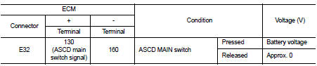
Is the inspection result normal? YES >> INSPECTION END
NO >> Go to EC-1009, "Diagnosis Procedure".
Diagnosis Procedure
1.CHECK ASCD MAIN SWITCH POWER SUPPLY CIRCUIT
1. Turn ignition switch OFF.
2. Disconnect combination switch (spiral cable) harness connector.
3. Turn ignition switch ON.
4. Check voltage between combination switch (spiral cable) harness connector and ground.
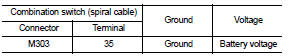
Is the inspection result normal? YES >> GO TO 3.
NO >> GO TO 2.
2.DETECT MALFUNCTIONING PART
Check the following.
• Combination switch (spiral cable)
• 10 A fuse (No. 2)
• Harness for open and short between combination switch (spiral cable) and
ground.
>> Repair open circuit, short to ground or short to power in harness or connectors.
3.CHECK ASCD MAIN SWITCH INPUT SIGNAL CIRCUIT FOR OPEN AND SHORT
1. Turn ignition switch OFF.
2. Disconnect ECM harness connector.
3. Check the continuity between ECM harness connector and combination switch (spiral cable) harness connector.
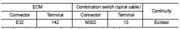
4. Also check harness for short to ground and short to power.
Is the inspection result normal? YES >> GO TO 5.
NO >> GO TO 4.
4.DETECT MALFUNCTIONING PART
Check the following.
• Harness connector E105, M77 • Combination switch (spiral cable) • Harness for open and short between ECM and combination switch (spiral cable)
>> Repair open circuit, short to ground or short to power in harness or connectors.
5.CHECK ASCD STEERING SWITCH
Refer to EC-1010, "Component Inspection".
Is the inspection result normal? YES >> GO TO 6.
NO >> Replace ASCD steering switch.
6.CHECK INTERMITTENT INCIDENT
Refer to GI-42, "Intermittent Incident", ???INCIDENT SIMULATION TESTS??? and ???GROUND INSPECTION???.
>> INSPECTION END
Component Inspection
1.CHECK ASCD STEERING SWITCH-I
1. Turn ignition switch OFF.
2. Disconnect combination switch (spiral cable) harness connector.
3. Check the continuity between combination switch (spiral cable) harness connector terminals under the following condition.
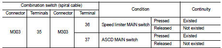
Is the inspection result normal? YES >> GO TO 2.
NO >> Replace ASCD steering switch.
2.CHECK ASCD STEERING SWITCH-II
Check resistance between combination switch (spiral cable) harness connector terminals under the following conditions.
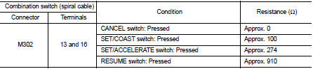
Is the inspection result normal? YES >> INSPECTION END
NO >> Replace ASCD steering switch.
 PC415 communication circuit
Description
CAN (Controller Area Network) is a serial communication line for real time
application. It is an on-vehicle multiplex
communication line with high data communication speed and excellen ...
 ASCD steering switch
Component Function Check
1.CHECK ASCD STEERING SWITCH FUNCTION
1. Turn ignition switch ON.
2. Check the voltage between ECM harness connector terminals under the following
conditions.
Is the i ...
Other materials:
Cockpit
1. Outside mirror remote control switch
2. Headlight, fog light and turn signal switch
— Headlight
— Turn signal light
— Fog light
3. Steering wheel
— Electric power steering system
— Horn
— Driver’s supplemental air bag
4. Wiper and washer switch
5. Shift lever
†...
Steering switch ground circuit
Description
Transmits the steering switch signal to audio unit.
Diagnosis Procedure
1.CHECK STEERING SWITCH SIGNAL GROUND CIRCUIT
1. Disconnect audio unit connector and spiral cable connector.
2. Check continuity between audio unit harness connector and spiral cable
harness connector.
Is t ...
Preparation
Special Service Tools
BASIC INSPECTION
STEERING WHEEL
Inspection
NEUTRAL POSITION STEERING WHEEL
1. Make sure that steering gear assembly, steering column assembly and
steering wheel are installed in the
correct position.
2. Perform neutral position inspection after wheel alignment. Refer ...
