Nissan Juke Service and Repair Manual : ASCD steering switch
Component Function Check
1.CHECK ASCD STEERING SWITCH FUNCTION
1. Turn ignition switch ON.
2. Check the voltage between ECM harness connector terminals under the following conditions.
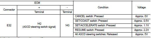
Is the inspection result normal? YES >> INSPECTION END
NO >> Go to EC-1011, "Diagnosis Procedure".
Diagnosis Procedure
1.CHECK GROUND CONNECTIONS
1. Turn ignition switch OFF.
2. Check ground connection E38. Refer to Ground inspection in GI-44, "Circuit Inspection".
Is the inspection result normal? YES >> GO TO 2.
NO >> Repair or replace ground connection.
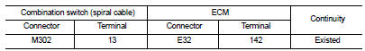
2.CHECK ASCD STEERING SWITCH CIRCUIT FOR OPEN AND SHORT
1. Turn ignition switch OFF.
2. Disconnect combination switch (spiral cable) harness connector.
3. Disconnect ECM harness connector.
4. Check the continuity between combination switch (spiral cable) harness connector and ECM harness connector.
5. Also check harness for short to ground and short to power.
Is the inspection result normal? YES >> GO TO 4.
NO >> GO TO 3.
3.DETECT MALFUNCTIONING PART
• Harness connector E105, M77 • Combination switch (spiral cable) • Harness for open or short between ECM and combination switch
>> Repair open circuit or short to ground or short to power in harness or connectors.
4.CHECK ASCD STEERING SWITCH INPUT SIGNAL CIRCUIT FOR OPEN AND SHORT
1. Check the continuity between combination switch (spiral cable) harness connector and ECM harness connector.

2. Also check harness for short to ground and short to power.
Is the inspection result normal? YES >> GO TO 6.
NO >> GO TO 5.
5.DETECT MALFUNCTIONING PART
• Harness connector E105, M77 • Combination switch (spiral cable) • Harness for open or short between ECM and combination switch (spiral cable)
>> Repair open circuit or short to ground or short to power in harness or connectors.
6.CHECK ASCD STEERING SWITCH
Refer to EC-1012, "Component Inspection".
Is the inspection result normal? YES >> GO TO 7.
NO >> Replace ASCD steering switch.
7.CHECK INTERMITTENT INCIDENT
Refer to GI-42, "Intermittent Incident", ???GROUND INSPECTION??? and ???INCIDENT SIMULATION TESTS???.
>> INSPECTION END
Component Inspection
1.CHECK ASCD STEERING SWITCH-I
1. Turn ignition switch OFF.
2. Disconnect combination switch (spiral cable) harness connector.
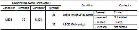
3. Check the continuity between combination switch (spiral cable) harness connector terminals under the following condition.
Is the inspection result normal? YES >> GO TO 2.
NO >> Replace ASCD steering switch.
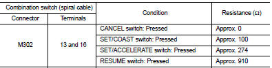
2.CHECK ASCD STEERING SWITCH-II
Check resistance between combination switch (spiral cable) harness connector terminals under the following conditions.
Is the inspection result normal? YES >> INSPECTION END
NO >> Replace ASCD steering switch.
 ASCD main switch
Component Function Check
1.CHECK ASCD MAIN SWITCH FUNCTION
1. Turn ignition switch ON.
2. Check the voltage between ECM harness connector terminals under the following
conditions.
Is the inspe ...
 CAN communication circuit
Description
CAN (Controller Area Network) is a serial communication line for real time
application. It is an on-vehicle multiplex
communication line with high data communication speed and excellen ...
Other materials:
Ambient sensor
Removal and Installation
REMOVAL
1. Remove bumper fascia assembly. Refer to EXT-13, "Removal and
Installation".
2. Disengage fixing pawl, and then remove ambient sensor (1)
from air guide RH.
: Pawl
3. Disconnect ambient sensor connector (2), and then remove
ambient sensor.
INS ...
Low pressure fuel pump
M/T models : Component Function Check
1.CHECK FUEL PUMP FUNCTION
1. Turn ignition switch ON.
2. Pinch fuel feed hose with two fingers.
NOTE:
Fuel pressure pulsation should be felt on the fuel feed hose for 1 second after
ignition switch is turned ON.
Is the inspection result normal?
YES ...
Seat belt warning light and chime
To ensure maximum safety for all occupants, your Nissan Leaf is equipped with an advanced seat belt reminder system for both the driver and front passenger positions. This system is designed to provide immediate visual and audible feedback if a seat belt remains unfastened whil ...
