Nissan Juke Service and Repair Manual : Basic inspection
DIAGNOSIS AND REPAIR WORKFLOW
Work Flow
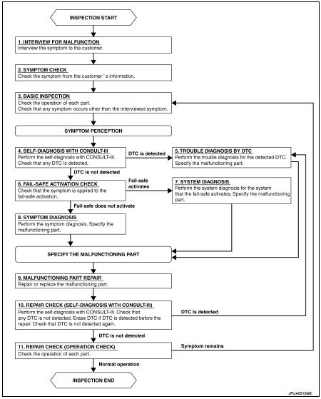
OVERALL SEQUENCE
DETAILED FLOW
1.INTERVIEW FOR MALFUNCTION
Interview the symptom to the customer.
>> GO TO 2.
2.SYMPTOM CHECK
Check the symptom from the customer's information.
>> GO TO 3.
3.BASIC INSPECTION
Check the operation of each part. Check that any symptom occurs other than the interviewed symptom.
>> GO TO 4.
4.SELF-DIAGNOSIS WITH CONSULT-III
Perform the self-diagnosis with CONSULT-III. Check that any DTC is detected.
Is any DTC detected? YES >> GO TO 5.
NO >> GO TO 6.
5.TROUBLE DIAGNOSIS BY DTC
Perform the trouble diagnosis for the detected DTC. Specify the malfunctioning part.
>> GO TO 9.
6.FAIL-SAFE ACTIVATION CHECK
Check that the symptom is applied to the fail-safe activation.
Does the fail-safe activate? YES >> GO TO 7.
NO >> GO TO 8.
7.SYSTEM DIAGNOSIS
Perform the system diagnosis for the system that the fail-safe activates. Specify the malfunctioning part.
>> GO TO 9.
8.SYMPTOM DIAGNOSIS
Perform the symptom diagnosis. Specify the malfunctioning part.
>> GO TO 9.
9.MALFUNCTION PART REPAIR
Repair or replace the malfunctioning part.
>> GO TO 10.
10.REPAIR CHECK (SELF-DIAGNOSIS WITH CONSULT-III)
Perform the self-diagnosis with CONSULT-III. Check that any DTC is not detected. Erase DTC if DTC is detected before the repair. Check that DTC is not detected again.
Is any DTC detected? YES >> GO TO 5.
NO >> GO TO 11.
11.REPAIR CHECK (OPERATION CHECK)
Check the operation of each part.
Does it operate normally? YES >> INSPECTION END
NO >> GO TO 3.
 Ecu diagnosis information
BCM, IPDM E/R
List of ECU Reference
...

Other materials:
License plate lamp circuit
Without daytime running light system
WITHOUT DAYTIME RUNNING LIGHT SYSTEM : Component Function Check
1.CHECK TAIL LAMP (RH) OPERATION
Check that the tail lamp (RH) is turned ON.
Is the inspection result normal?
YES >> GO TO 2.
NO >> Check tail lamp circuit. Refer to EXL-61, &qu ...
Push-button power switch
WARNING
Do not attempt to operate or cycle the push-button power switch while actively driving the vehicle except in a verified, extreme emergency situation. (The primary EV powertrain system completely shuts down and cuts propulsion when the power switch is pushed rapidly three conse ...
For side and rollover collision : When SRS is activated in a collision
CAUTION:
Due to varying models and option levels, not all parts listed in the chart below
apply to all vehicles.
WORK PROCEDURE
1. Before performing any of the following steps, ensure that all vehicle body
and structural repairs have been
completed.
2. Replace the following components:
â ...
