Nissan Juke Service and Repair Manual : Back door opener actuator
Diagnosis Procedure
1.CHECK BACK DOOR OPENER ACTUATOR INPUT SIGNAL
1. Turn ignition switch OFF.
2. Disconnect back door opener assembly connector.
3. Check voltage between back door opener assembly harness connector and ground.
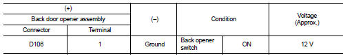
Is the inspection result normal? YES >> GO TO 3.
NO >> GO TO 2.
2.CHECK BACK DOOR OPENER ACTUATOR CIRCUIT
1. Disconnect BCM connector.
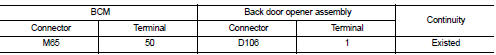
2. Check continuity between BCM harness connector and back door opener assembly harness connector.
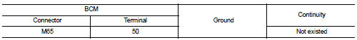
3. Check continuity between BCM harness connector and ground.
Is the inspection result normal? YES >> Replace BCM. Refer to BCS-161, "Removal and Installation".
NO >> Repair or replace harness.
3.CHECK BACK DOOR OPENER ACTUATOR GROUND CIRCUIT
Check continuity between back door opener assembly harness connector and ground.
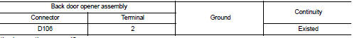
Is the inspection normal? YES >> Replace back door opener assembly.
NO >> Repair or replace harness.

 Back door opener switch
Component Function Check
1.CHECK FUNCTION
1. Select ÔÇťTRUNKÔÇŁ of ÔÇťBCMÔÇŁ using CONSULT-III.
2. Select ÔÇťTRNK OPNR SWÔÇŁ in ÔÇťDATA MONITORÔÇŁ mode.
3. Check that the function operates normall ...
Other materials:
P0744 torque converter
Description
This malfunction is detected when the torque converter clutch does not
lock-up as instructed by the TCM. This
is not only caused by electrical malfunction (circuits open or shorted), but
also by mechanical malfunction such
as control valve sticking, improper solenoid valve operati ...
LAN System can system (type 8)
DTC/CIRCUIT DIAGNOSIS
Main line between IPDM-E and DLC circuit
Diagnosis Procedure
1.CHECK CONNECTOR
1. Turn the ignition switch OFF.
2. Disconnect the battery cable from the negative terminal.
3. Check the following terminals and connectors for damage, bend and loose
connection (connector s ...
P1226 TP sensor
DTC Logic
DTC DETECTION LOGIC
DTC CONFIRMATION PROCEDURE
1.PRECONDITIONING
If DTC Confirmation Procedure has been previously conducted, always perform
the following procedure
before conducting the next test.
1. Turn ignition switch OFF and wait at least 10 seconds.
2. Turn ignition swit ...
