Nissan Juke Service and Repair Manual : Back door opener switch
Component Function Check
1.CHECK FUNCTION
1. Select “TRUNK” of “BCM” using CONSULT-III.
2. Select “TRNK OPNR SW” in “DATA MONITOR” mode.
3. Check that the function operates normally according to the following conditions.
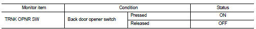
Is the inspection result normal? YES >> Back door opener switch is OK.
NO >> Refer to DLK-513, "Diagnosis Procedure".
Diagnosis Procedure
1.CHECK BACK DOOR OPEN INPUT SIGNAL
1. Turn ignition switch OFF.
2. Disconnect back door opener switch connector.
3. Check signal between back door opener switch harness connector and ground using oscilloscope.
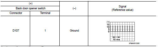
Is the inspection result normal? YES >> GO TO 3.
NO >> GO TO 2.
2.CHECK BACK DOOR OPENER SWITCH CIRCUIT
1. Disconnect BCM connector.
2. Check continuity between BCM harness connector and back door opener switch harness connector.
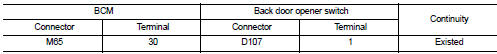
3. Check continuity between BCM harness connector and ground.
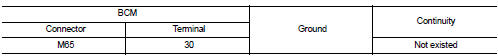
Is the inspection result normal? YES >> Replace BCM. Refer to BCS-161, "Removal and Installation".
NO >> Repair or replace harness.
3.CHECK BACK DOOR OPENER SWITCH GROUND CIRCUIT
Check continuity between back door opener switch harness connector and ground.
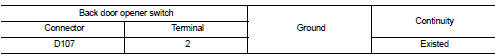
Is the inspection result normal? YES >> GO TO 4.
NO >> Repair or replace harness.
4.CHECK BACK DOOR OPENER SWITCH
Refer to DLK-514, "Component Inspection".
Is the inspection result normal? YES >> GO TO 5.
NO >> Replace back door opener switch.
5.CHECK INTERMITTENT INCIDENT
Refer to GI-42, "Intermittent Incident".
>> INSPECTION END
Component Inspection
1.CHECK BACK DOOR OPENER SWITCH
1. Turn ignition switch OFF.
2. Disconnect back door opener switch connector.
3. Check continuity between back door opener switch terminals.
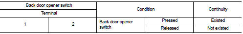
Is the inspection result normal? YES >> INSPECTION END
NO >> Replace back door opener switch.
 Back door opener actuator
Diagnosis Procedure
1.CHECK BACK DOOR OPENER ACTUATOR INPUT SIGNAL
1. Turn ignition switch OFF.
2. Disconnect back door opener assembly connector.
3. Check voltage between back door opener assembl ...
 Door lock actuator
Driver side
DRIVER SIDE : Component Function Check
1.CHECK FUNCTION
1. Select “DOOR LOCK” of “BCM” using CONSULT-III.
2. Select “DOOR LOCK” in “ACTIVE TEST” mode.
3. Check that th ...
Other materials:
Service data and specifications (SDS)
SERVICE DATA AND SPECIFICATIONS (SDS)
Idle Speed
*: Under the following conditions
• A/C switch: OFF
• Electric load: OFF (Lights, heater fan & rear window defogger)
• Steering wheel: Kept in straight-ahead position
Ignition Timing
*: Under the following conditions
• A/C swit ...
P0746 pressure control solenoid A
Description
The line pressure solenoid valve regulates the oil pump discharge pressure to
suit the driving condition in
response to a signal sent from the TCM.
DTC Logic
DTC DETECTION LOGIC
DTC CONFIRMATION PROCEDURE
CAUTION:
Always drive vehicle at a safe speed.
NOTE:
If “DTC CONFIRM ...
How to read the displayed lines
Guiding lines which indicate the vehicle width and distances to objects with
reference to the bumper lineA are displayed on the monitor.
Distance guide lines:
Indicate distances from the bumper.
• Red line1 : approx. 1.5 ft (0.5 m)
• Yellow line2 : approx. 3 ft (1 m)
• Green line3 : a ...
